Maintenance

4.4.2Torque Requirements

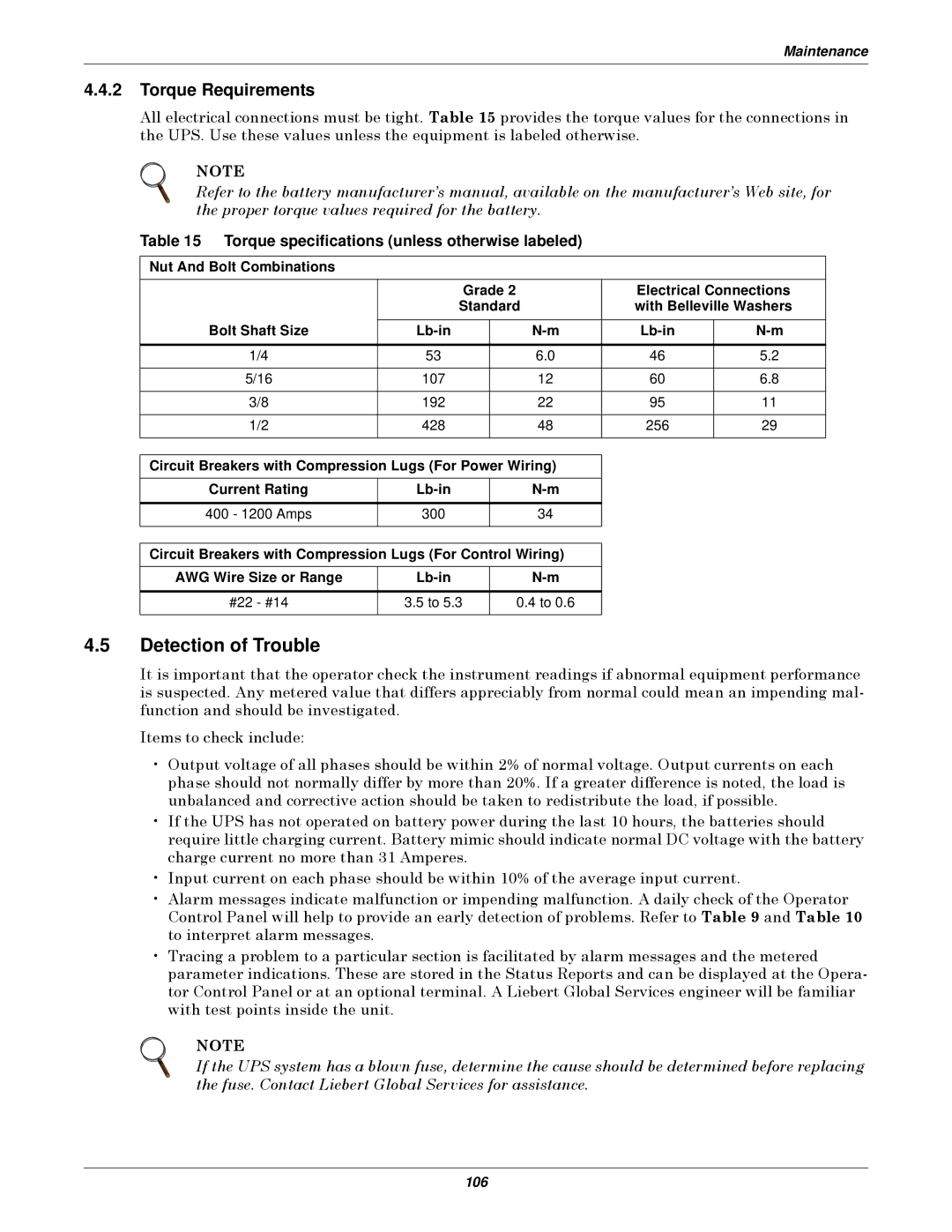
All electrical connections must be tight. Table 15 provides the torque values for the connections in the UPS. Use these values unless the equipment is labeled otherwise.

NOTE

Refer to the battery manufacturer’s manual, available on the manufacturer’s Web site, for the proper torque values required for the battery.

Table 15 Torque specifications (unless otherwise labeled)

Nut And Bolt Combinations


Grade 2


Electrical Connections


Standard


with Belleville Washers

Bolt Shaft Size


Lb-in


N-m

Lb-in

N-m


1/4

53


6.0

46

5.2


5/16

107


12

60

6.8


3/8

192


22

95

11


1/2

428


48

256

29


Circuit Breakers with Compression Lugs (For Power Wiring)


Current Rating

Lb-in


N-m


400 - 1200 Amps

300


34


Circuit Breakers with Compression Lugs (For Control Wiring)


AWG Wire Size or Range

Lb-in


N-m


#22 - #14

3.5 to 5.3


0.4 to 0.6


4.5Detection of Trouble

It is important that the operator check the instrument readings if abnormal equipment performance is suspected. Any metered value that differs appreciably from normal could mean an impending mal- function and should be investigated.

Items to check include:

Output voltage of all phases should be within 2% of normal voltage. Output currents on each phase should not normally differ by more than 20%. If a greater difference is noted, the load is unbalanced and corrective action should be taken to redistribute the load, if possible.

If the UPS has not operated on battery power during the last 10 hours, the batteries should require little charging current. Battery mimic should indicate normal DC voltage with the battery charge current no more than 31 Amperes.

Input current on each phase should be within 10% of the average input current.

Alarm messages indicate malfunction or impending malfunction. A daily check of the Operator Control Panel will help to provide an early detection of problems. Refer to Table 9 and Table 10 to interpret alarm messages.

Tracing a problem to a particular section is facilitated by alarm messages and the metered parameter indications. These are stored in the Status Reports and can be displayed at the Opera- tor Control Panel or at an optional terminal. A Liebert Global Services engineer will be familiar with test points inside the unit.

NOTE

If the UPS system has a blown fuse, determine the cause should be determined before replacing the fuse. Contact Liebert Global Services for assistance.

106

Page 112
Image 112
Emerson Series 610 manual Detection of Trouble, Torque Requirements, Torque specifications unless otherwise labeled

Series 610 specifications

The Emerson Series 610 is a cutting-edge solution for precise process measurement and control, designed specifically for industries where accuracy and reliability are paramount. This advanced instrument, often utilized in oil and gas, chemical processing, and water treatment sectors, combines innovative technology with robust features to meet the demanding requirements of modern industrial applications.

One of the standout features of the Series 610 is its exceptional measurement accuracy. The device employs advanced sensor technology that enables precise determination of variables such as pressure, temperature, and flow. This accuracy translates into improved process efficiency and enhanced product quality. With a wide range of measurement capabilities, the Series 610 can handle varying process conditions and fluid types, making it versatile across different applications.

The heart of the Emerson Series 610 lies in its intelligent diagnostics and predictive maintenance functionalities. This built-in technology allows for real-time monitoring of the device's operational status, providing valuable insights into performance trends. By detecting anomalies early, users can take proactive measures to prevent potential failures, thereby reducing downtime and maintenance costs.

Moreover, the Series 610 is designed with user-friendly features. Its intuitive interface and easy-to-navigate menus facilitate quick setup and configuration, enabling operators to be productive from the outset. The device also supports various communication protocols, including HART and FOUNDATION fieldbus, ensuring seamless integration into existing control systems and enhancing overall automation capabilities.

Another notable characteristic of the Emerson Series 610 is its robust construction. Designed to withstand harsh environmental conditions, it is built with durable materials that offer high resistance to corrosion and physical damage. This durability ensures longevity and reliability, even in the most challenging industrial environments.

In summary, the Emerson Series 610 represents a significant advancement in process measurement technology. With its exceptional accuracy, intelligent diagnostics, user-friendly design, and robust construction, it is an ideal choice for industries seeking to enhance their operational efficiency and reliability. Its ability to seamlessly integrate into existing systems further solidifies its position as a leading solution in the field of industrial measurement and control. As industries continue to evolve, the Series 610 is poised to meet the challenges of the future with confidence and precision.