Liebert Series 610 UPS
AC Power
For Business-Critical Continuity
BATTERY CABINET PRECAUTIONS
CONTACTING LIEBERT FOR SUPPORT
TABLE OF CONTENTS
4.0 MAINTENANCE
5.0 SPECIFICATIONS
FIGURES
TABLES
IMPORTANT SAFETY INSTRUCTIONS
SAVE THESE INSTRUCTIONS
1.1 System Description
1.0 INTRODUCTION
Figure 1 Multi-Module UPS, 100-500kVA
Figure 2 Multi-Module UPS, 500-750kVA
1.2 Reliability
Types of System Control Cabinets SCCs
Designed for Success
Figure 3 System Control Cabinets
1.3 Safety Precautions
1.4.2 Input Power Failure
1.4 Modes of Operation
Other Factors to Consider
1.4.7 Maintenance Bypass
1.4.8 Off-Battery
1.4.3 Recharge
1.4.4 Overload
Introduction
1. Battery
1.6 Options
2. Battery Racks or Cabinets
2.1 General Component Descriptions
2.0 THEORY OF OPERATION
2.1.1 System Control Cabinet
2.1.3 Battery Plant
Figure 6 UPS module block diagram
2.1.2 UPS Module
2.2 Detailed Component Descriptions
2.2.1 Controls Hardware
Software
Input Power Factor
2.2.2 Rectifier/Charger
Operation
Input Circuit Breaker
2.2.3 Battery Charging Circuit
Battery Disconnect
Battery Charge Current Limiting
Battery Equalize Charge Circuit
Non-Linear Load Characteristics
Unbalanced Load Characteristics
2.2.4 Inverter
Operation
Figure 7 System Control Cabinet block diagram
2.2.5 Static Bypass
Fuse Protection
Shorted SCR Monitoring
Static Switch Isolation
Pulsed Parallel Operation
Load Transfers
Transfer and Retransfer Conditions
1. Automatic Transfers to Bypass
2. Manual Transfers
3. Transfer Inhibited
2.2.6 Redundant Mode
6. Retransfer Inhibited
Features
3.1 Display Screen and Operator Controls
3.0 OPERATION
Figure 8 Typical operator controls
Typical operator controls
Operation
500kVA
Figure 9 Operator controls, typical SCCT System Control Cabinet
Typical SCCT System Control Cabinet operator controls
Operation
Figure 10 Liebert Series 610 UPS and SCC operator control panels
Liebert Series 610 UPS and SCC operator control panels
Operation
Figure 11 Switches behind SCC control panel door
Liebert Series 610 UPS and SCC operator control panels
Operation
3.2 Menu Tree Navigation
Figure 12 Menu tree
3.2.1 Master Menu Screen
Figure 13 SCC and module master menu screens
From any primary screen accessed directly from the Master Menu, pushing the Select pad once will return you to the Master Menu. From any secondary screen, pushing the Select pad twice will return you to the Master Menu
3.2.2 SCC Monitor/Mimic Display Screen
Input Metering Displays
Output Metering Displays
Figure 14 SCC Monitor/Mimic display screen
Status/Alarm Message Areas
Item 7 - Alarm Messages
Item 5 - Module Status Messages
Item 6 - System Status Messages
BATTERY VOLTS AMPS 15 CHARG
3.2.3 Module Monitor/Mimic Display Screen
Input Metering Displays
Output Metering Displays
Alarm Messages
Item 5 - Alarm Messages
Figure 16 Monitor/Mimic display example Normal power flow
Operation
SCC Display
Module Display
Figure 17 Monitor/Mimic display example Utility fail
Operation
Operation
270 kVA / 217 kW
325A 325A 325A
Operation
MOD 1 ON LINE MVODLTS2 OFF540 LINE SUM ALM MODAMPS3 75ON15 CHARGLINE
A B C 953A3780A 953A3780A 953A378A0A
50.0Hz 5060..00Hz
Operation
MODAMPS3 75OFFCHARGLINE SUM ALM
3.2.4 Walk-In Display Screen
Figure 21 Walk-in display screen during start-up
3.2.5 Status Reports Screens
Present Status
Each of the four Status Reports can be displayed on a remote terminal
Refer to 3.2.15 - Communication Interfaces
Event History
Figure 23 Present status report screens, SCC above and module
Figure 24 Event history report screen
Operation
History Status
Figure 25 History status report screens
Table 5 Alarm conditions that freeze history data gathering
Alarm in SCC
Alarm in Module
Figure 26 Battery cycle monitor screen
System Status
Figure 27 Battery cycle monitoring summary screen
Battery Cycle Monitoring Summary
Event
Date
3.2.6 System Configuration Screens
Figure 29 SCC system configuration screen
Date
Figure 30 Date screen
Time
Figure 31 Time screen
Figure 32 Auto dial setting screen
Auto Dial
Modem Baud Rate
Maximum Auto-Retransfer Attempts
Figure 33 Modem baud rate
Figure 34 Maximum auto-retransfer attempts screen
System Current Rating
Language Selection
System Options
Figure 35 SCC system options screen
Figure 37 Battery test screen-MMU only
Figure 38 Battery test results screen
Continuous Duty Static Switch Optional
Figure 39 Monitor/Mimic display example Continuous Duty Static Switch
Remote Monitor
SCC and module remote monitor indications
3.2.7 Alarm Limit Settings Screen
Figure 40 Module alarm limit settings screen
Battery Float Voltage
Temperature Limit Setting Optional
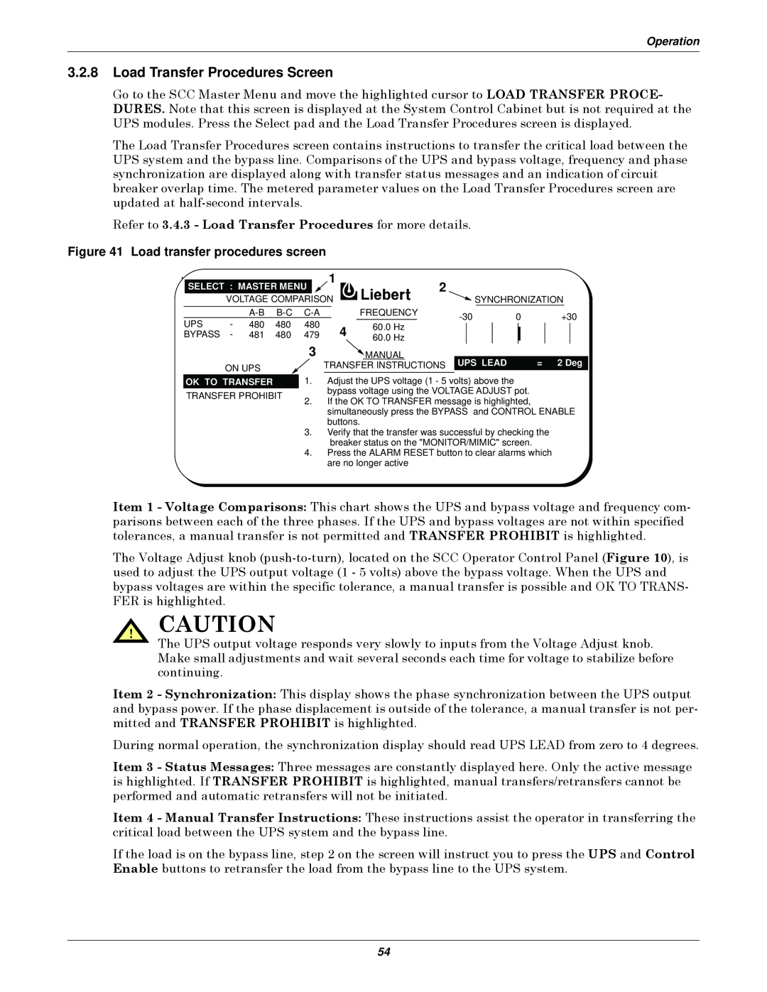
3.2.8 Load Transfer Procedures Screen
Figure 41 Load transfer procedures screen
3.2.9 Start-Up Procedures Screen
Figure 42 SCC start- up procedures screen
3.2.10 Shutdown Procedures Screen
Figure 43 Module start- up procedures screens
Figure 44 SCC shutdown procedures screen
Figure 45 Module shutdown procedures screen
3.2.11 Battery Time Screen Module Only
Figure 46 Battery time screen 15 minute discharge
Figure 47 Battery time screen 45-minute discharge
Figure 48 Accuracy range of values for calculated battery times
Remaining
Time
Battery age Excessive battery discharge/recharge cycles
Loose electrical connections Ambient temperature extremes
Dirty battery jar covers
Bad or weak cells Low acid levels in flooded cells
3.2.12 Meter Calibration Screen
Figure 49 Meter calibration screen
3.2.13 Battery Equalize Screen
Figure 50 Battery equalize screen
3.2.14 Alarm and Status Messages Module Status Messages
Figure 51 SCC status and alarm message areas
System Status Messages
Alarm Messages
Table 8 Abbreviations used in alarm messages
Load Block Messages
Alarm messages - meaning and corrective action
Operation
Alarm messages - meaning and corrective action continued
Operation
Alarm messages - meaning and corrective action continued
Refer to 3.2.14 - Alarm and Status Messages
Operation
Alarm messages - meaning and corrective action continued
Operation
Determine the cause of the emergency condition and correct it if possible
Table 10 Alarm messages - summary
Alarm Message
Operation
Special Functions
3.2.15 Communication Interfaces
Worldwide Reporting
Auto-Dial
Requesting Information
Local Reporting to a Terminal
Local Reporting to a Monitor
Site Reporting SiteScan or SNMP
Table 11 Liebert Series 610 terminal commands
Remote Monitor Panel
Separate / Simultaneous Outputs
3.3 Modes of Operation
Table 12 Circuit breaker abbreviations
Abbreviation
Circuit Breaker
3.3.1 Load on Bypass
3.3.2 OK to Transfer
SCCT
Figure 52 Load on bypass, UPS not available
SCCT
SCCT
Figure 53 Load on bypass, UPS available
Figure 54 Load on UPS, bypass available
Figure 55 Momentary overload, pulsed static bypass switch
SCCT
3.3.3 Momentary Overloads
SCCT
3.3.4 Input Power Failure-Load on Battery
Figure 56 Input power fail-load on battery
SCCT
3.3.5 One Module Off-Line
SCCT
Figure 57 One module off-line, load on UPS
3.3.6 Off Battery
Figure 58 Load on UPS-battery not available
SCCT
3.3.7 Emergency Modules Off
SCCT
Figure 59 Emergency modules off
3.3.8 Remote Emergency Power Off
Figure 60 Emergency power off
SCCT
3.3.10 Maintenance Bypass
3.3.9 System Shutdown
SCCT
Figure 61 System shutdown
Figure 62 Load on maintenance bypass, two breakers
Figure 63 Load on maintenance bypass, three breakers
SCCT
SCCT
3.4 Manual Procedures
3.4.1 SCC Start-Up Procedure
Step 1. Before you apply power to the UPS modules, determine the position of the following circuit breakers and switches
5. Set the Static Switch Disconnects to ON closed
Figure 64 SCC start-up procedures screen
3.4.2 UPS Module Start-Up
Figure 65 Module start-up procedures screen
The Battery block in the Monitor/Mimic Display indicates the battery voltage and charge current
3.4.3 Load Transfer Procedures
Figure 66 Load transfer procedures screen
3.4.4 Maintenance Bypass Load Transfers
If the load is on Maintenance Bypass
If the load is on the UPS System Bypass
3.4.5 Shutdown Procedures System Shutdown Procedure
Figure 67 SCC shutdown procedures screen
Module Shutdown Procedure
Figure 68 Module shutdown procedures screen
Remote Emergency Power Off REPO
3.5 Automatic Operations
Local Emergency Modules Off LEMO
3.5.1 Overloads Without Transfer
3.5.2 Automatic Transfers to Bypass
Figure 69 Current-versus-time curves of module overload capacity
3.5.3 Automatic Retransfers to UPS
3.5.4 Automatic Module Off-Line
3.5.5 Automatic Emergency Modules Off
4.1 Safety Precautions
4.0 MAINTENANCE
4.2 Liebert Global Services
Maintenance Agreements The Signature Program
Professional Start-Up
Training
4.3 Routine Maintenance
4.3.1 Record Log
4.3.2 Air Filters
4.3.3 Limited Life Components
4.4 Battery Maintenance
4.4.1 Battery Safety Precautions
Battery Safety Precautions In French Per CSA Requirements
AVERTISSEMENT
Instructions Importantes Concernant La Sécurité
Conserver Ces Instructions
Matching Battery Cabinets Optional
Battery Voltage VDC
Number of Cells
Nominal
Table 13 Battery retorque values
Table 14 Battery voltage record
Rack-Mounted Batteries
Table 15 Torque specifications unless otherwise labeled
4.5 Detection of Trouble
4.4.2 Torque Requirements
4.6 Reporting a Problem
4.9 Upstream Feeder Circuit Breaker Setting Inspections
4.7 Corrective Actions
4.8 Recommended Test Equipment
5.0 SPECIFICATIONS
Figure 70 Output power envelope for 0.8 and 0.9 pf rated units
5.1 Rating
Table 17 Specifications applicable to environment
Specifications
5.2 Environmental Conditions
5.3 Adjustments
5.4 Battery Operation
5.5 Electrical Specifications
Specifications
System overload capacity depends on
Specifications
Page
Ensuring The High Availability
Of Mission-Critical Data And Applications
Technical Support / Service
reduced capital equipment and operating costs