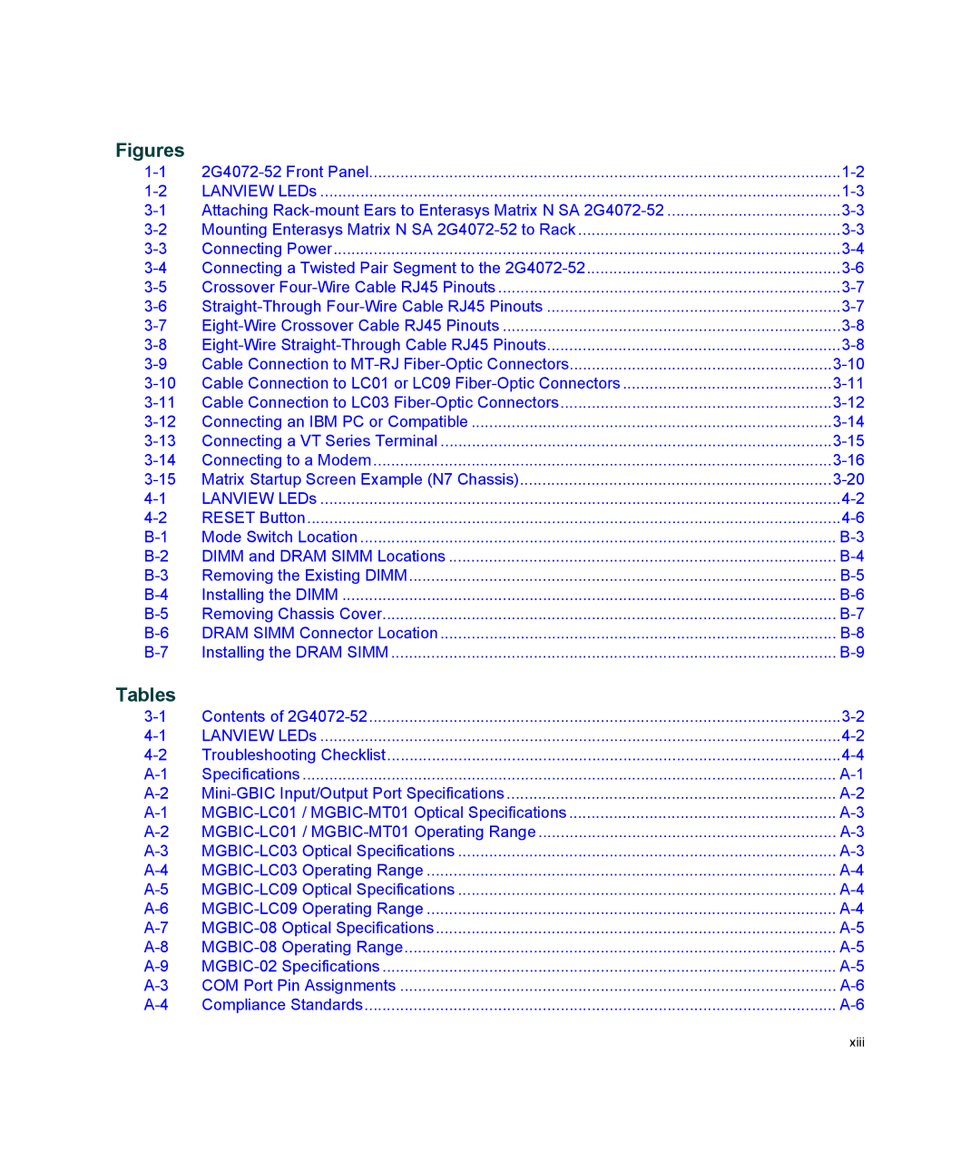
Figures

1-1

2G4072-52 Front Panel

1-2

1-2

LANVIEW LEDs

1-3

3-1

Attaching Rack-mount Ears to Enterasys Matrix N SA 2G4072-52

3-3

3-2

Mounting Enterasys Matrix N SA 2G4072-52 to Rack

3-3

3-3

Connecting Power

3-4

3-4

Connecting a Twisted Pair Segment to the 2G4072-52

3-6

3-5

Crossover Four-Wire Cable RJ45 Pinouts

3-7

3-6

Straight-ThroughFour-Wire Cable RJ45 Pinouts

3-7

3-7

Eight-Wire Crossover Cable RJ45 Pinouts

3-8

3-8

Eight-WireStraight-Through Cable RJ45 Pinouts

3-8

3-9

Cable Connection to MT-RJFiber-Optic Connectors

3-10

3-10

Cable Connection to LC01 or LC09 Fiber-Optic Connectors

3-11

3-11

Cable Connection to LC03 Fiber-Optic Connectors

3-12

3-12

Connecting an IBM PC or Compatible

3-14

3-13

Connecting a VT Series Terminal

3-15

3-14

Connecting to a Modem

3-16

3-15

Matrix Startup Screen Example (N7 Chassis)

3-20

4-1

LANVIEW LEDs

4-2

4-2

RESET Button

4-6

B-1

Mode Switch Location

B-3

B-2

DIMM and DRAM SIMM Locations

B-4

B-3

Removing the Existing DIMM

B-5

B-4

Installing the DIMM

B-6

B-5

Removing Chassis Cover

B-7

B-6

DRAM SIMM Connector Location

B-8

B-7

Installing the DRAM SIMM

B-9

Tables

3-1

Contents of 2G4072-52

3-2

4-1

LANVIEW LEDs

4-2

4-2

Troubleshooting Checklist

4-4

A-1

Specifications

A-1

A-2

Mini-GBIC Input/Output Port Specifications

A-2

A-1

MGBIC-LC01 /MGBIC-MT01 Optical Specifications

A-3

A-2

MGBIC-LC01 /MGBIC-MT01 Operating Range

A-3

A-3

MGBIC-LC03 Optical Specifications

A-3

A-4

MGBIC-LC03 Operating Range

A-4

A-5

MGBIC-LC09 Optical Specifications

A-4

A-6

MGBIC-LC09 Operating Range

A-4

A-7

MGBIC-08 Optical Specifications

A-5

A-8

MGBIC-08 Operating Range

A-5

A-9

MGBIC-02 Specifications

A-5

A-3

COM Port Pin Assignments

A-6

A-4

Compliance Standards

A-6

xiii

Page 15
Image 15
Enterasys Networks 2G4072-52 manual Figures, Tables