Memory Locations and Replacement Procedures
Removing the DRAM SIMM
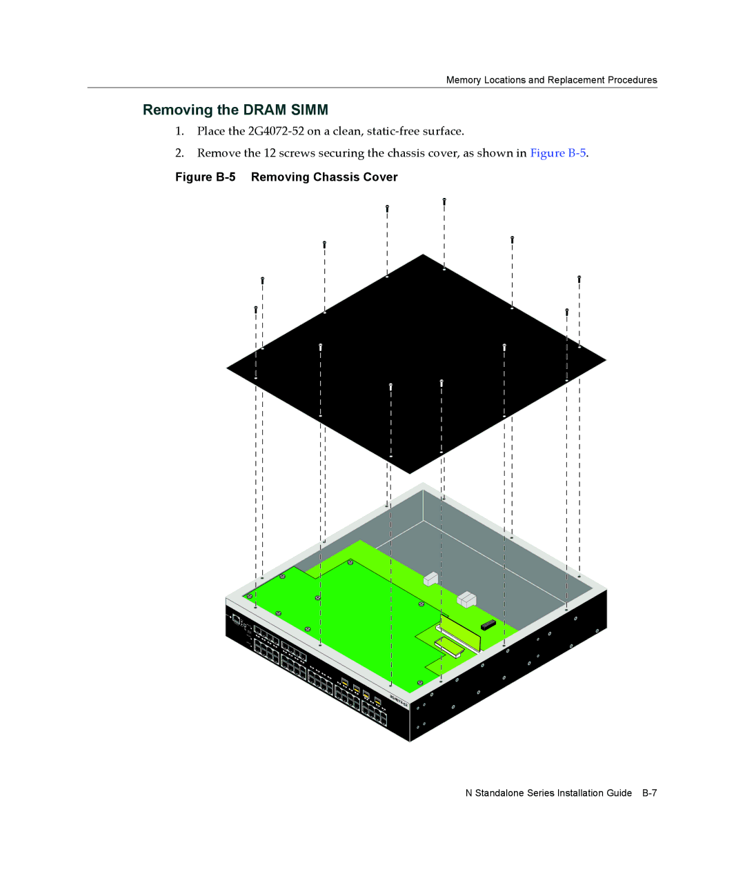
1.Place the 2G4072‐52 on a clean, static‐free surface.
2.Remove the 12 screws securing the chassis cover, as shown in Figure B‐5.
Figure B-5 Removing Chassis Cover
RESET
| CPU |
|
|
CONSOLE | PWR | GROUP3 |
|
|
| G |
|
|
| SROU |
|
|
| ELECPT |
|
|
| GROUP2 | 1 |
|
| GROUP1 | 2 |
|
| 3 |
4![]()
5![]()
6![]()
![]() 7
7![]() 8
8![]()
9![]()
10
11
12
13
14
15![]()
![]()
![]()
16
17
18
19
20
N Standalone Series Installation Guide