Memory Locations and Replacement Procedures
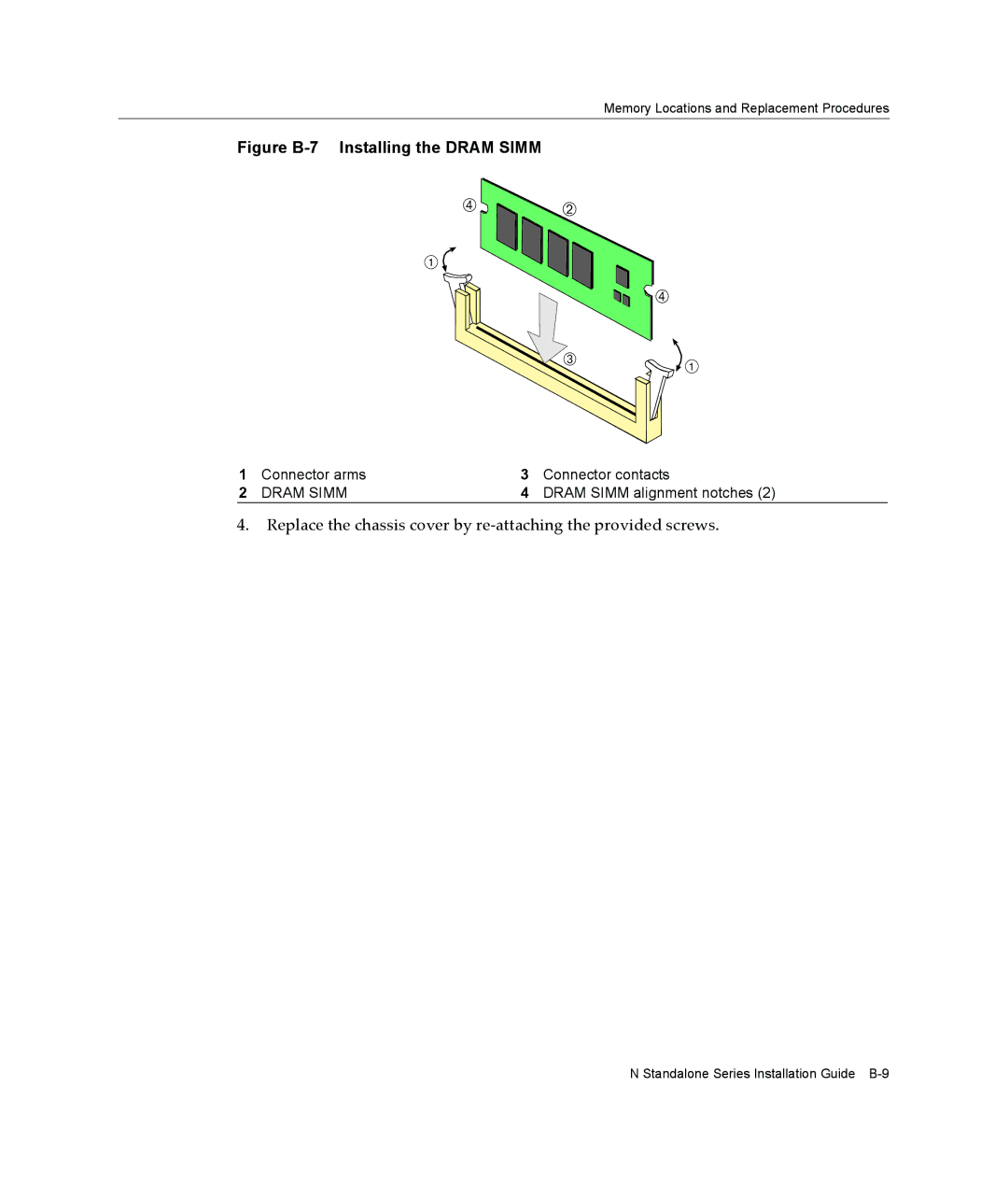
Figure B-7 Installing the DRAM SIMM
à Á
1
| Ã |
 | 1 |
|
1 | Connector arms | 3 | Connector contacts |
2 | DRAM SIMM | 4 | DRAM SIMM alignment notches (2) |
4.Replace the chassis cover by re‐attaching the provided screws.
N Standalone Series Installation Guide