Installing Optional Network Expansion Modules
Removing the Coverplate
Refer to Figure 3‐1 and proceed as follows:
1.Attach the antistatic wrist strap (refer to the instructions on the antistatic wrist strap package).
2.Place the DFE‐Gold module on an antistatic pad on a sturdy flat surface.
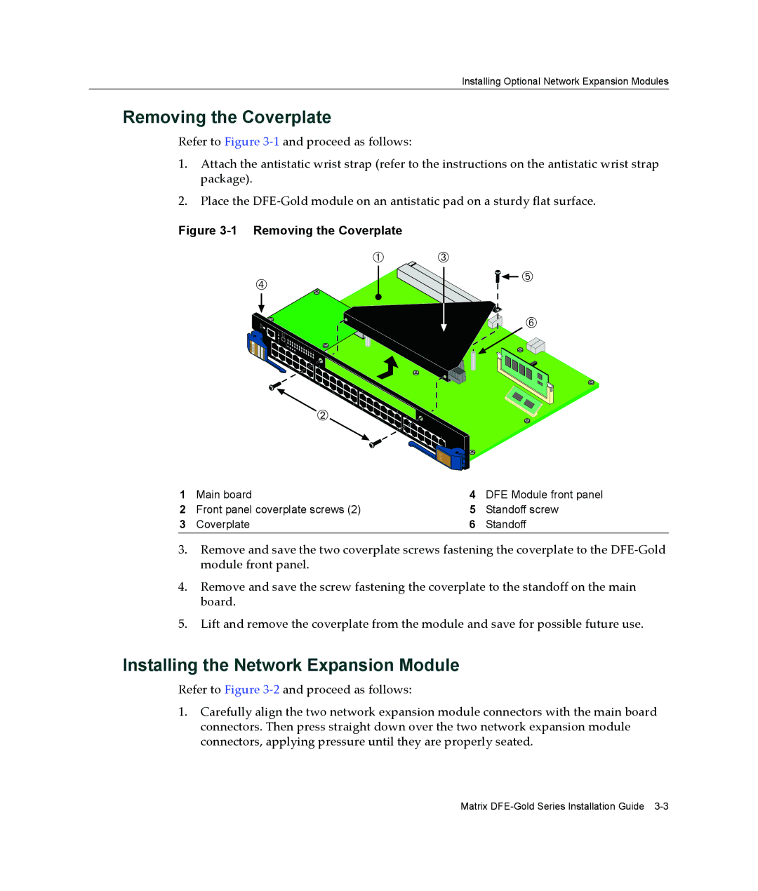
Figure 3-1 Removing the Coverplate
Ã
ENETGb |
ÀÂ
![]() Ä
Ä
Å
Á
![]()
![]() DFE
DFE
1 | Main board | 4 | DFE Module front panel |
2 | Front panel coverplate screws (2) | 5 | Standoff screw |
3 | Coverplate | 6 | Standoff |
3.Remove and save the two coverplate screws fastening the coverplate to the DFE‐Gold module front panel.
4.Remove and save the screw fastening the coverplate to the standoff on the main board.
5.Lift and remove the coverplate from the module and save for possible future use.
Installing the Network Expansion Module
Refer to Figure 3‐2 and proceed as follows:
1.Carefully align the two network expansion module connectors with the main board connectors. Then press straight down over the two network expansion module connectors, applying pressure until they are properly seated.
Matrix