Setting the Mode Switches
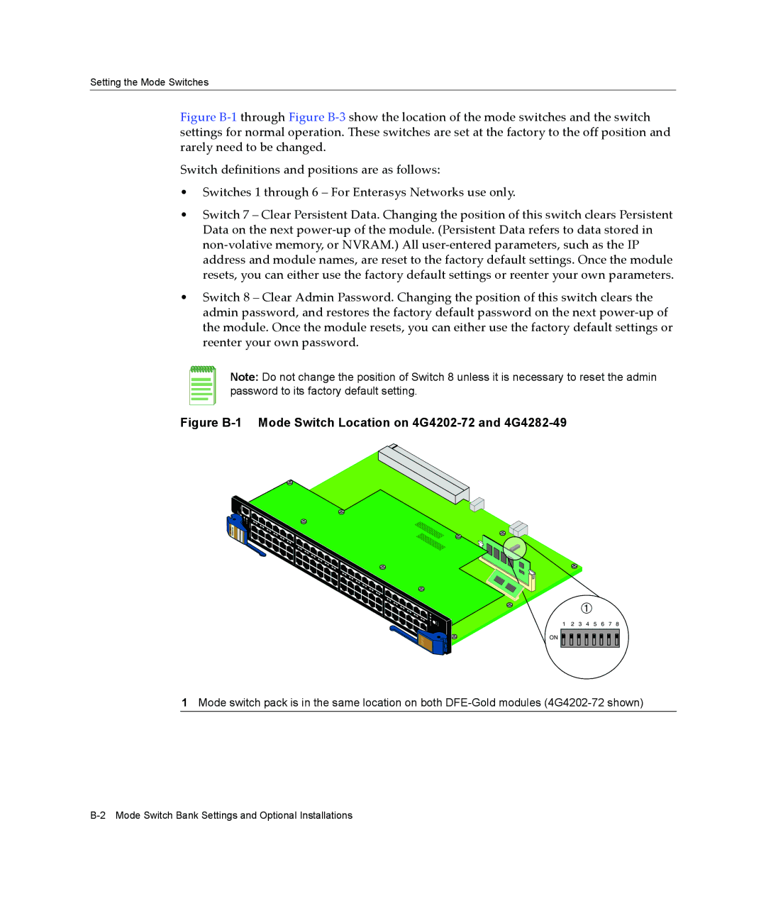
Figure B‐1 through Figure B‐3 show the location of the mode switches and the switch settings for normal operation. These switches are set at the factory to the off position and rarely need to be changed.
Switch definitions and positions are as follows:
•Switches 1 through 6 – For Enterasys Networks use only.
•Switch 7 – Clear Persistent Data. Changing the position of this switch clears Persistent Data on the next power‐up of the module. (Persistent Data refers to data stored in non‐volative memory, or NVRAM.) All user‐entered parameters, such as the IP address and module names, are reset to the factory default settings. Once the module resets, you can either use the factory default settings or reenter your own parameters.
•Switch 8 – Clear Admin Password. Changing the position of this switch clears the admin password, and restores the factory default password on the next power‐up of the module. Once the module resets, you can either use the factory default settings or reenter your own password.
Note: Do not change the position of Switch 8 unless it is necessary to reset the admin password to its factory default setting.
Figure B-1 Mode Switch Location on 4G4202-72 and 4G4282-49
ENETGb
2824 94-
G4
À
1 2 3 4 5 6 7 8 ON ![]()
![]()
![]()
![]()
![]()
![]()
![]()
![]()
![]()
![]()
![]()
1Mode switch pack is in the same location on both