Memory Locations and Replacement Procedures
Installing the DRAM SIMM on 4G4282-49
Caution: Observe all Electrostatic Discharge (ESD) precautions when handling sensitive electronic equipment.
Precaución: Al trabajar con equipos electrónicos sensibles, tome todas las precauciones de seguridad para evitar descargas de electricidad estática.
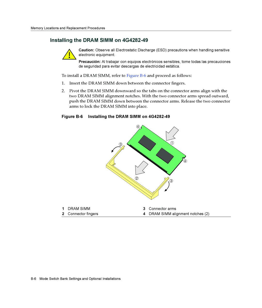
To install a DRAM SIMM, refer to Figure B‐6 and proceed as follows:
1.Insert the DRAM SIMM down between the connector fingers.
2.Pivot the DRAM SIMM downward so the tabs on the connector arms align with the two DRAM SIMM alignment notches. With the two connector arms spread outward, push the DRAM SIMM down between the connector arms. Release the two connector arms to lock the DRAM SIMM into place.
Figure B-6 Installing the DRAM SIMM on 4G4282-49
Ã
|
| Â | À |
|
|
| |
|
|
| Ã |
|
| Á | Â |
|
|
| |
1 | DRAM SIMM | 3 | Connector arms |
2 | Connector fingers | 4 | DRAM SIMM alignment notches (2) |