Enterasys Matrix
Page
Page
Regulatory Compliance Information
Electromagnetic Compatibility EMC
Supplement to Product Instructions
Vcci Notice
Safety Information Class 1 Laser Transceivers
Enterasys NETWORKS, INC. Firmware License Agreement
Viii
Page
Page
Contents
Appendix a Specifications
Troubleshooting
Appendix B Mode Switch Bank Settings Optional Installations
Index
Figures
Tables
Who Should Use This Guide
About This Guide
Important Notice
Related Documents
How to Use This Guide
For Refer to
Following conventions are used in this guide
Conventions Used in This Guide
Conventions Used in This Guide Xvi About This Guide
For information about Refer to
Introduction
DFE-Gold Modules and Interface Options
Overview of DFE Series Capabilities
4G4282-49
4G4202-72
4G4202-72 and 4G4282-49 DFE-Gold Modules
7G-6MGBIC and 7G-6MGBIC-A Gigabit Ethernet Interface Modules
Connectivity
Switch Configuration Using WebView
Management
Standards Compatibility
Switch Configuration Using CLI Commands
Secure Networks Policy Support
Getting Help
Lanview Diagnostic LEDs
Link Aggregation
Network Requirements
100BASE-TX Network
10BASE-T Network
1000BASE-SX/LX/ELX Network
1000BASE-T Network
1000BASE-T Network Network Requirements
Important Notice
Installation
Contents of DFE-Gold Module Carton Quantity
Installing Optional Network Expansion Modules
Unpacking the DFE-Gold Module
Removing the Coverplate
Installing the Network Expansion Module
Installing the Network Expansion Module
Preparation
Installing an Optional Mini-GBIC
Mini-GBIC with MT-RJ Connector
Installation
Mini-GBIC with LC Connector
Removing the Mini-GBIC
N5 POE
Module Placement and Rules
Example 2 -6, B
Example 1 -6, a
Example 3 -6, C
Example 4 -6, D
Installing the DFE Module into a Chassis
To install the module, refer to ‐1 and proceed as follows
Installing Module into Matrix E7 or N7 Chassis
Card guides
Installing Module into Matrix N1, N3, or N5 Chassis
Installing Module into N1, N3, or N5 Chassis only N3 shown
Connecting to the Network
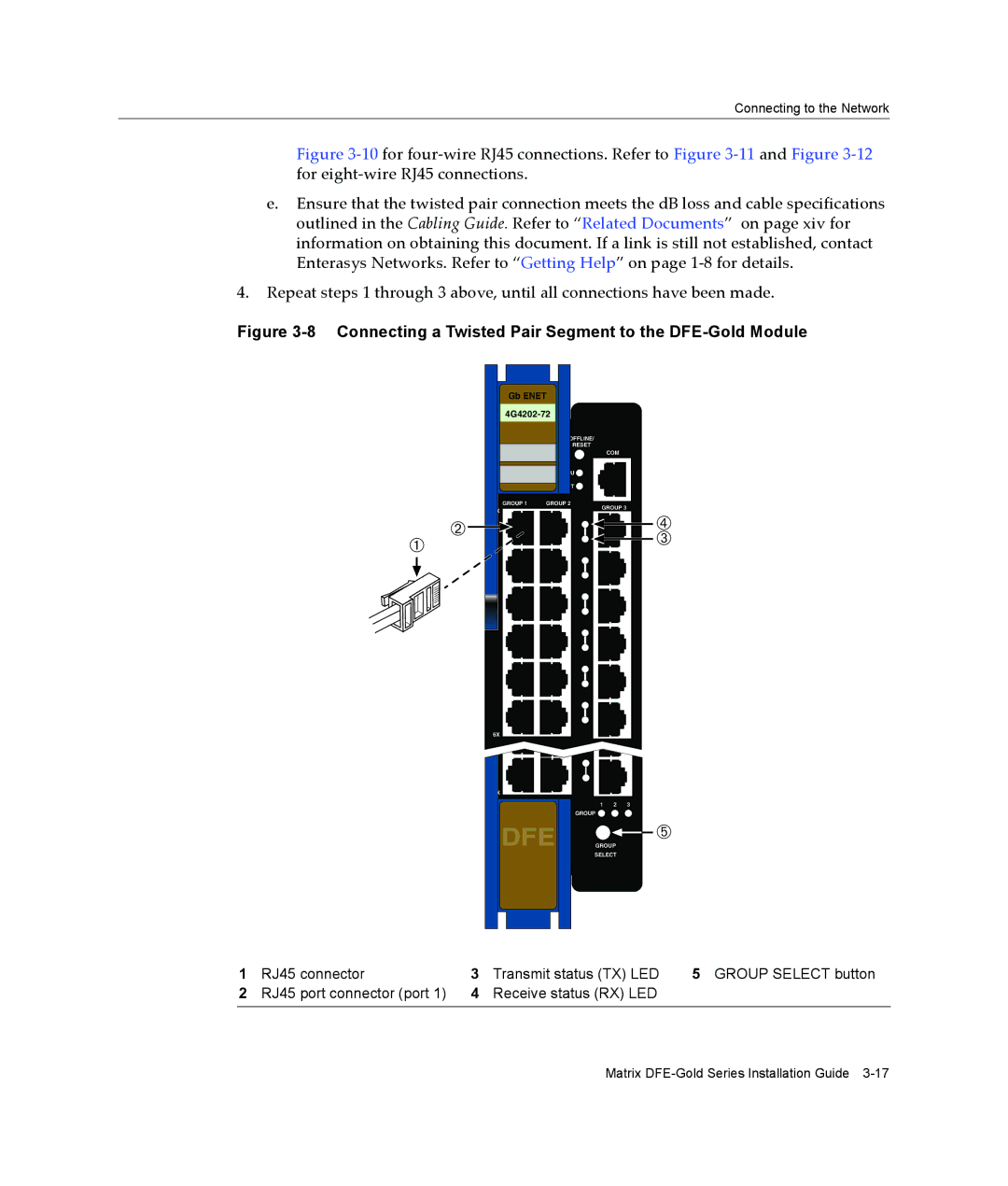
Connecting UTP Cables
DFE
RX+ TX+
TX1+ RX1 TX2+ TX3+ RX3 RX2 TX4+ RX4
Connecting Fiber-Optic Cables to Mini-GBICs
13 Cable Connection to MT-RJ Fiber-Optic Connectors
14 Cable Connection to LC Fiber-Optic Connectors
What Is Needed
Connecting to COM Port for Local Management
Parameter Setting
Connecting to an IBM PC or Compatible Device
15 Connecting an IBM PC or Compatible Device
Connecting to a VT Series Terminal
16 Connecting a VT Series Terminal
Connecting to a Modem
17 Connecting to a Modem
COM Port Adapter Wiring and Signal Diagram RJ45
Adapter Wiring and Signal Assignments
VT Series Port Adapter Wiring and Signal Diagram
RJ45 DB25
Completing the Installation of a New System
Completing the Installation
Modem Port Adapter Wiring and Signal Diagram
First-Time Log-In Using a Console Port Connection
18 Matrix DFE Startup Screen Example N7 Chassis
Logging in with an Administratively-Configured User Account
Using Lanview
Troubleshooting
About the Management Mgmt LED
4G4282-49
Viewing the Receive and Transmit Activity
Color State Recommended Action
LED
Amber Alternating 67% on, 33% and off off. Indicates that a
Refer to the Matrix DFE-Gold Series Configuration
Troubleshooting Checklist
Matrix DFE-Gold Series Configuration Guide for
DFE-Gold Module Shutdown Procedure
OFFLINE/RESET Switch
Recommended Shutdown Procedure Using OFFLINE/RESET Switch
Last Resort Shutdown Procedure Using OFFLINE/RESET Switch
DFE-Gold Module Specifications
Specifications
Table A-1 Specifications
Processors/Memory
Ethernet Interface Module Specifications
Table A-3 Mini-GBIC Input/Output Port Specifications
Mini-GBIC Input/Output Specifications
MGBIC-LC01 / MGBIC-MT01 Specifications 1000BASE-SX
Gigabit Ethernet Specifications
MGBIC-LC03 Specifications 1000BASE-LX
MGBIC-08 Specifications 1000BASE-ELX
MGBIC-LC09 Specifications 1000BASE-LX
Table A-10 MGBIC-08 Optical Specifications
Table A-12 MGBIC-02 Specifications
MGBIC-02 Specifications 1000BASE-T
Table A-11 MGBIC-08 Operating Range 1550 nm
Regulatory Compliance
COM Port Pinout Assignments
Table A-14 Compliance Standards Regulatory Compliance
Regulatory Compliance Specifications
Setting the Mode Switches
Mode Switch Bank Settings Optional Installations
Required Tools
Figure B-1 Mode Switch Location on 4G4202-72 and 4G4282-49
Location of Dram Simm and Dimm Memory Modules
Memory Locations and Replacement Procedures
Removing the Dram Simm
Dram Simm Replacement Procedure
Figure B-5 Removing the Existing Dram Simm from 4G4282-49
Figure B-6 Installing the Dram Simm on 4G4282-49
Installing the Dram Simm on 4G4282-49
Removing the Dimm
Dimm Replacement Procedure
Figure B-8 Installing the Dimm on 4G4202-72 or 4G4282-49
Installing the Dimm on 4G4202-72 or 4G4282-49
Numerics
Index
Index-2