Installing Optional Network Expansion Modules
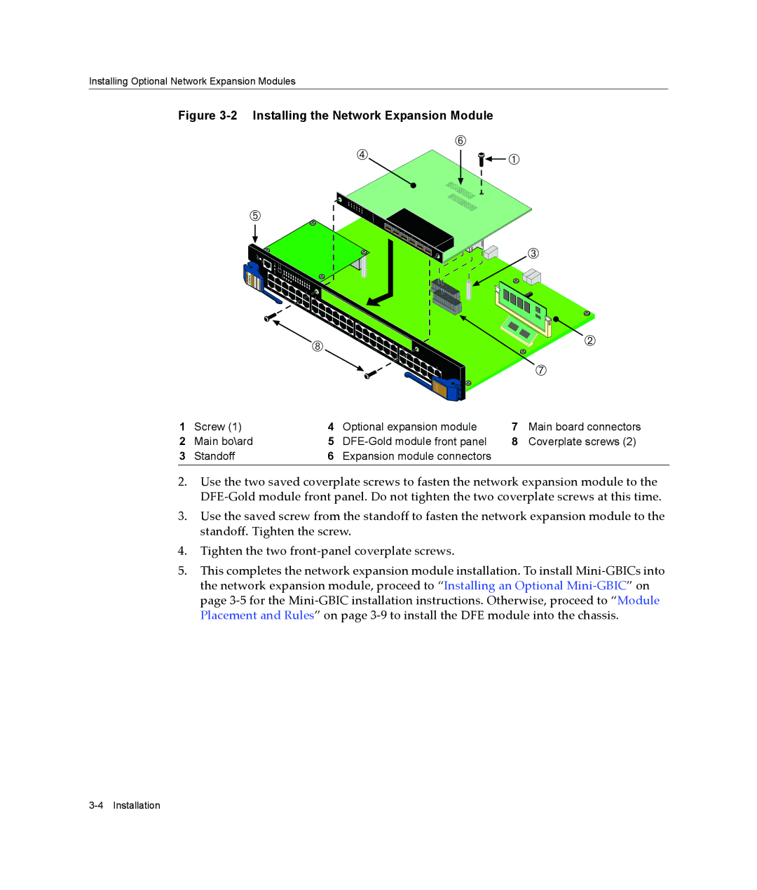
Figure 3-2 Installing the Network Expansion Module
Å
à ![]()
![]() À
À
Ä
ENETGb | |
| 4 |
6 ![]() 5
5 ![]() 4 3 2 1
4 3 2 1
A - 6MGBIC - 7G
1
2
3
4
5
6
Ç![]()
![]()
![]() DFE
DFE
Â
Á
Æ
1 | Screw (1) | 4 | Optional expansion module | 7 | Main board connectors |
2 | Main bo\ard | 5 | 8 | Coverplate screws (2) | |
3 | Standoff | 6 | Expansion module connectors |
|
|
2.Use the two saved coverplate screws to fasten the network expansion module to the DFE‐Gold module front panel. Do not tighten the two coverplate screws at this time.
3.Use the saved screw from the standoff to fasten the network expansion module to the standoff. Tighten the screw.
4.Tighten the two front‐panel coverplate screws.
5.This completes the network expansion module installation. To install Mini‐GBICs into the network expansion module, proceed to “Installing an Optional Mini‐GBIC” on page 3‐5 for the Mini‐GBIC installation instructions. Otherwise, proceed to “Module Placement and Rules” on page 3‐9 to install the DFE module into the chassis.