Control Software, cont’d
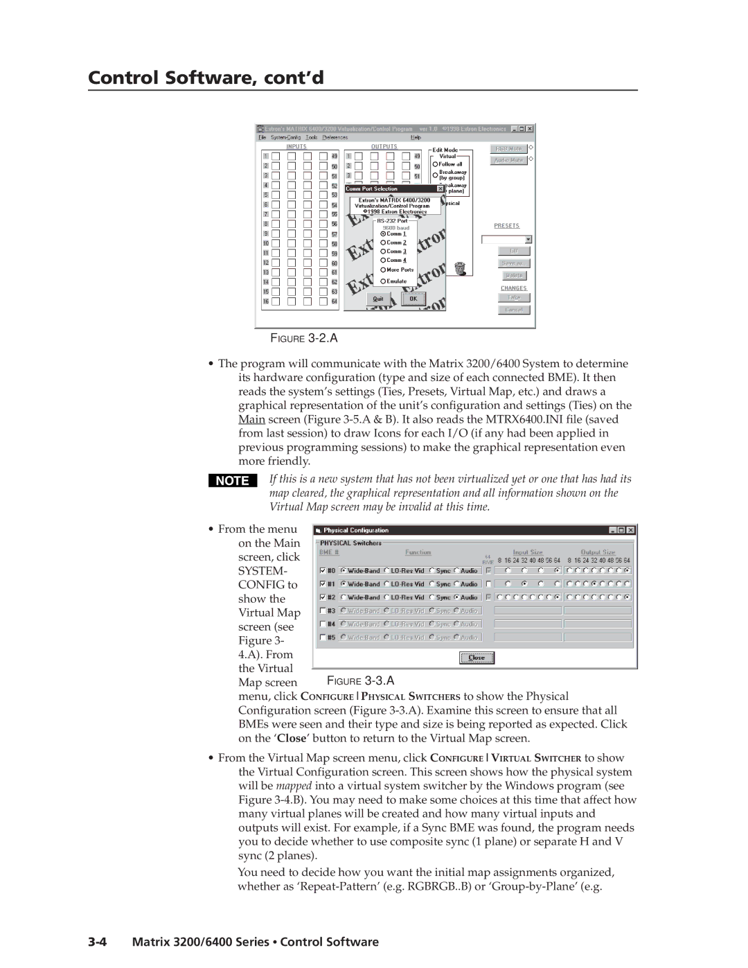
FIGURE 3-2.A
•The program will communicate with the Matrix 3200/6400 System to determine its hardware configuration (type and size of each connected BME). It then reads the system’s settings (Ties, Presets, Virtual Map, etc.) and draws a graphical representation of the unit’s configuration and settings (Ties) on the Main screen (Figure
If this is a new system that has not been virtualized yet or one that has had its map cleared, the graphical representation and all information shown on the Virtual Map screen may be invalid at this time.
•From the menu on the Main screen, click
SYSTEM- CONFIG to show the Virtual Map
screen (see |
|
Figure 3- |
|
4.A). From |
|
the Virtual | FIGURE |
Map screen |
menu, click CONFIGUREPHYSICAL SWITCHERS to show the Physical Configuration screen (Figure
•From the Virtual Map screen menu, click CONFIGUREVIRTUAL SWITCHER to show the Virtual Configuration screen. This screen shows how the physical system will be mapped into a virtual system switcher by the Windows program (see Figure
You need to decide how you want the initial map assignments organized, whether as
