Installation, cont’d
4. Connecting the RS-232/RS-422 Cable to BME #0
Connect the cable from the Host PC computer serial port to the
5. Connecting the AC Power Cable(s) to the BME(s)
Each BME has its own internal power supply. Connect an AC Power cord to the AC power receptacle on each BME (Item 4 in Figure
6. Applying AC Power to the BME(s)
Each BME has a power ON/OFF toggle switch on the rear panel just above the AC power cord receptacle. BME #0 must be powered ON at the same time or after all other BMEs are ON. Press each power switch to the ON (1) position, Go to 6A on Page
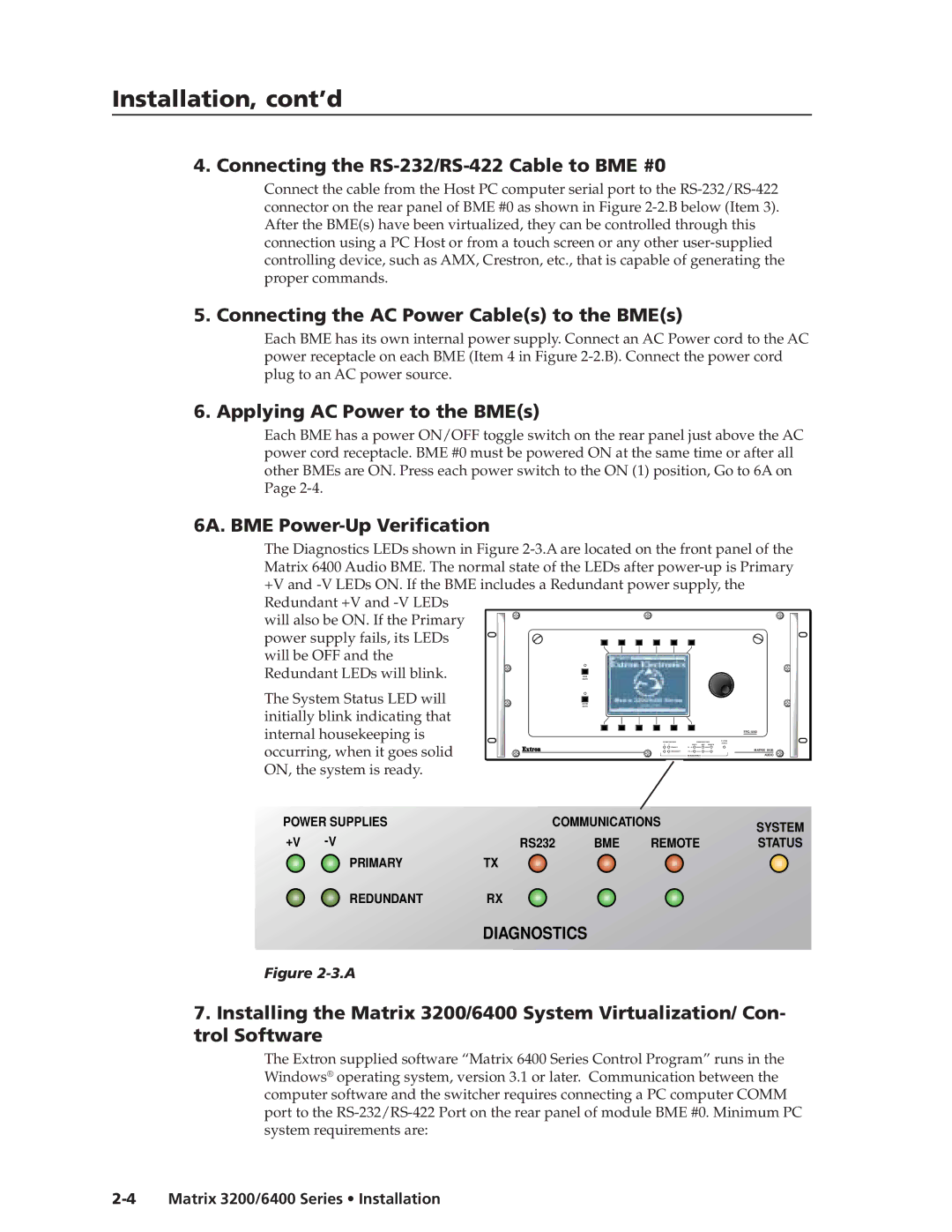
6A. BME Power-Up Verification
The Diagnostics LEDs shown in Figure
Matrix 6400 Audio BME. The normal state of the LEDs after | |||||
+V and | |||||
Redundant +V and |
|
|
|
|
|
will also be ON. If the Primary |
|
|
|
|
|
power supply fails, its LEDs |
|
|
|
|
|
will be OFF and the |
|
|
|
|
|
Redundant LEDs will blink. |
| RGB |
|
|
|
| MUTE |
|
|
| |
The System Status LED will |
| AUDIO |
|
|
|
| MUTE |
|
|
| |
initially blink indicating that |
|
|
|
|
|
internal housekeeping is |
|
|
|
| |
|
| POWER SUPPLIES | COMMUNICATIONS | SYSTEM | |
|
| STATUS | |||
occurring, when it goes solid |
|
| +V | RS232 BME REMOTE |
|
|
| PRIMARY | TX |
| |
|
| REDUNDANT | RX | MATRIX 6400 | |
|
|
| DIAGNOSTICS | AUDIO | |
ON, the system is ready. |
|
|
|
|
|
POWER SUPPLIES | COMMUNICATIONS |
| SYSTEM | ||
+V |
|
|
|
| |
RS232 | BME | REMOTE | STATUS | ||
PRIMARY | TX |
|
|
|
|
REDUNDANTRX
DIAGNOSTICS
Figure 2-3.A
7.Installing the Matrix 3200/6400 System Virtualization/ Con- trol Software
The Extron supplied software “Matrix 6400 Series Control Program” runs in the Windows® operating system, version 3.1 or later. Communication between the computer software and the switcher requires connecting a PC computer COMM port to the