Extron electronic 3200s manual Programmer’ser’sGuide,Guidecont’d, Serial Communications Port

Models: 3200s

1 70
Download 70 pages 58.1 Kb
Page 34
Image 34
Programmer’ser’sGuide,Guidecont’d

Programmer’ser’sGuide,Guidecont’d

Serial Communications Port

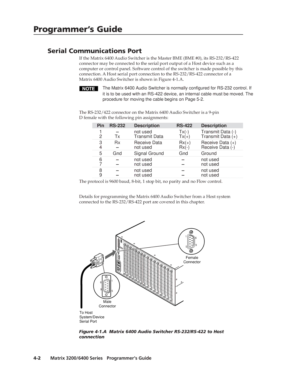
If the Matrix 6400 Audio Switcher is the Master BME (BME #0), its RS-232/RS-422 connector may be connected to the serial port output of a Host device such as a computer or control panel. Software control of the switcher is made possible by this connection. A Host serial port connection to the RS-232/RS-422 connector of a Matrix 6400 Audio Switcher is shown in Figure 4-1.A.

The Matrix 6400 Audio Switcher is normally configured for RS-232 control. If it is to be used with an RS-422 device, an internal cable must be moved. The procedure for moving the cable begins on Page 5-2.

The RS-232/422 connector on the Matrix 6400 Audio Switcher is a 9-pin

D female with the following pin assignments:

Pin

RS-232

Description

RS-422

Description

1

not used

Tx(-)

Transmit Data (-)

2

Tx

Transmit Data

Tx(+)

Transmit Data (+)

3

Rx

Receive Data

Rx(+)

Receive Data (+)

4

not used

Rx(-)

Receive Data (-)

5

Gnd

Signal Ground

Gnd

Ground

6

not used

not used

7

not used

not used

8

not used

not used

9

not used

not used

The protocol is 9600 baud, 8-bit, 1 stop bit, no parity and no Flow control.

Details for programming the Matrix 6400 Audio Switcher from a Host system connected to the RS-232/RS-422 port are covered in this chapter.

1

6

A


BME

B


C


4

D


ADDRESS

E

COMM.

A

B


C

MKP


D


E


AN


MAAHE


DE INIM,CA


USA

IN


INSerial Communications Port IN4-2 Matrix 3200/6400 Series • Programmer’s Guide

INManual background

INPUTS INManual background INManual backgroundManual background INManual background

INManual background IN

5

9

OUT

COMM.

AC

BME

FUSE:POWER

250V

5INPUT.


0A TT


50/60Hz


0.5A MAX


100-240V

6

1


1

-8

9-16

17-24

25-32 33-40 41-48

49-56

OUTManual backgroundManual background OUTManual backgroundManual background OUTManual background

OUTPUTS

OUTManual background

OUTManual background

OUTManual background

OUTManual background

OUTManual background

Female

Connector

9

5


Male

Connector

57-


64


1

-8

9-16 17-24

25-32 Manual backgroundManual background 33-40 Manual background 41-48 49-56

57-64

To Host

System/Device

Serial Port

Figure 4-1.A Matrix 6400 Audio Switcher RS-232/RS-422 to Host connection

4-2 Matrix 3200/6400 Series Programmer’s Guide

Page 34
Image 34
Extron electronic 3200s manual Programmer’ser’sGuide,Guidecont’d, Serial Communications Port