|
| BME |
|
| - |
|
| 4 |
|
| + |
A | ADDRESS | |
B |
|
|
C | COMM. |
|
D |
| |
E |
|
|
A | MKP |
|
B |
| |
C |
|
|
D |
|
|
E | ANAHEIM, CA | |
| MADE IN USA | |
| RS232/RS422 |
|
OUT | COMM.BME |
|
IN |
|
|
AC POWER INPUT |
| |
FUSE: 250V 5.0A TT | POWER CORD BEFORE SERVICING | |
| 5.0A MAX 50/60Hz | |
| DISCONNECT | |
|
|
| INPUTS |
|
|
|
|
|
| OUTPUTS |
|
|
| ||
IN | IN | IN | IN | IN | IN | IN | IN | OUT | OUT | OUT | OUT | OUT | OUT | OUT | OUT |
1 - 8 | 9 - 16 | 17 - 24 | 25 - 32 | 33 - 40 | 41 - 48 | 49 - 56 | 57 - 64 | 1 - 8 | 9 - 16 | 17 - 24 | 25 - 32 | 33 - 40 | 41 - 48 | 49 - 56 | 57 - 64 |
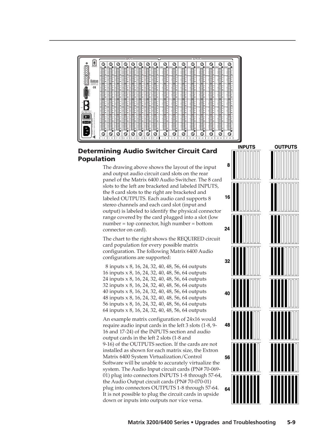
Determining Audio Switcher Circuit Card Population
The drawing above shows the layout of the input and output audio circuit card slots on the rear
panel of the Matrix 6400 Audio Switcher. The 8 card slots to the left are bracketed and labeled INPUTS,
the 8 card slots to the right are bracketed and
labeled OUTPUTS. Each audio card supports 8 stereo channels and each card slot (input and
output) is labeled to identify the physical connector range covered by the card plugged into a slot (low
number = top connector, high number = bottom connector on card).
The chart to the right shows the REQUIRED circuit card population for every possible matrix configuration. The following Matrix 6400 Audio configurations are supported:
8 inputs x 8, 16, 24, 32, 40, 48, 56, 64 outputs 16 inputs x 8, 16, 24, 32, 40, 48, 56, 64 outputs 24 inputs x 8, 16, 24, 32, 40, 48, 56, 64 outputs 32 inputs x 8, 16, 24, 32, 40, 48, 56, 64 outputs 40 inputs x 8, 16, 24, 32, 40, 48, 56, 64 outputs 48 inputs x 8, 16, 24, 32, 40, 48, 56, 64 outputs 56 inputs x 8, 16, 24, 32, 40, 48, 56, 64 outputs 64 inputs x 8, 16, 24, 32, 40, 48, 56, 64 outputs
An example matrix configuration of 24x16 would require audio input cards in the left 3 slots
16and
Matrix 6400 System Virtualization/Control Software will be unable to accurately virtualize the system. The Audio Input circuit cards (PN#
01) plug into connectors INPUTS
plug into connectors OUTPUTS
Matrix 3200/6400 Series • Upgrades and Troubleshooting |