Upgrades and Troubleshooting, cont’d
Changing the Audio Output Card Gain Jumpers
The gain indicated by an FPC 1000 LCD panel or a Host computer running Extron’s Matrix 6400 System Control software may be off by 6dB depending on the type of output (balanced or unbalanced) and jumper positions on the Audio Output card. If the Audio card jumpers for each output are set to match the output type, the indicated gain will match the actual gain for all outputs.
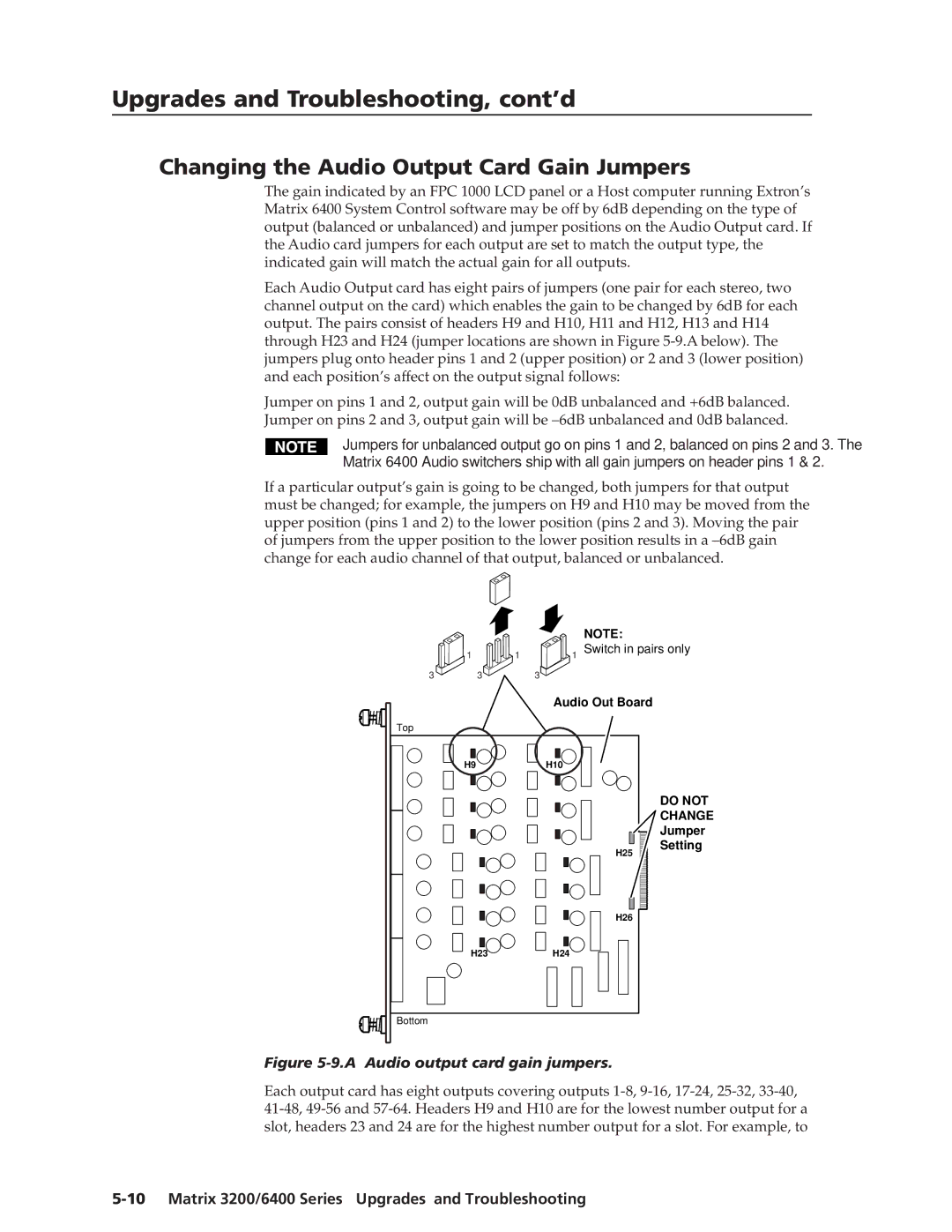
Each Audio Output card has eight pairs of jumpers (one pair for each stereo, two channel output on the card) which enables the gain to be changed by 6dB for each output. The pairs consist of headers H9 and H10, H11 and H12, H13 and H14 through H23 and H24 (jumper locations are shown in Figure
Jumper on pins 1 and 2, output gain will be 0dB unbalanced and +6dB balanced. Jumper on pins 2 and 3, output gain will be
Jumpers for unbalanced output go on pins 1 and 2, balanced on pins 2 and 3. The
Matrix 6400 Audio switchers ship with all gain jumpers on header pins 1 & 2.
If a particular output’s gain is going to be changed, both jumpers for that output must be changed; for example, the jumpers on H9 and H10 may be moved from the upper position (pins 1 and 2) to the lower position (pins 2 and 3). Moving the pair of jumpers from the upper position to the lower position results in a
|
|
| NOTE: |
| 1 | 1 | 1 Switch in pairs only |
3 | 3 |
| 3 |
|
|
| Audio Out Board |
Top
H9
H10
H25
DO NOT
CHANGE
Jumper
Setting
H26
H23
H24
Bottom
Figure 5-9.A Audio output card gain jumpers.
Each output card has eight outputs covering outputs