486-33 MHz CPU or equivalent with 16 MB RAM 5 MB Hard Disk space for software
If your Matrix 3200/6400 switcher was previously setup for RS-232, and your PC Comm port uses RS-422, the switcher must be changed to match the PC interface. The procedure for making the change begins on Page 5-2.
The first floppy disk (1 of 2) has instructions printed on the label. The software must be installed onto the hard drive. It cannot be run from the floppy disk
1.Installing the software from the 3.5” floppy disk onto the hard disk is like most other Windows programs. (Run Setup.exe from the first floppy disk.)
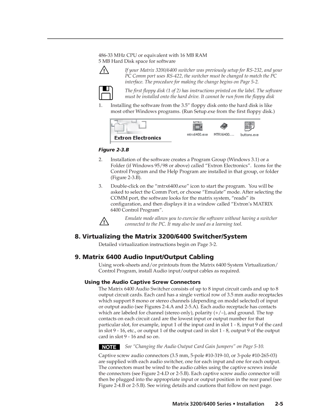
Figure 2-3.B
2.Installation of the software creates a Program Group (Windows 3.1) or a Folder (if Windows 95/98 or above) called “Extron Electronics”. Icons for the Control Program and the Help Program are installed in that group, or folder (Figure 2-3.B).
3.Double-click on the “mtrx6400.exe” icon to start the program. You will be asked to select the Comm Port, or choose “Emulate” mode. After selecting the COMM port, the software looks for the matrix system, “reads” its configuration, and then displays it in a window called “Extron’s MATRIX 6400 Control Program”.
Emulate mode allows you to exercise the software without having a switcher connected to the PC. It may also be used as a learning tool.
8. Virtualizing the Matrix 3200/6400 Switcher/System
Detailed virtualization instructions begin on Page 3-2.
9. Matrix 6400 Audio Input/Output Cabling
Using work-sheets and/or printouts from the Matrix 6400 System Virtualization/ Control Program, install Audio input/output cables as required.
Using the Audio Captive Screw Connectors
The Matrix 6400 Audio Switcher consists of up to 8 input circuit cards and up to 8 output circuit cards. Each card has a single vertical row of 3.5 mm audio receptacles which support 8 mono or stereo channels (depending on model selected) of input or output audio (see Figures 2-4.A and 2-5.A). Each audio receptacle has contacts which are labeled for channel (stereo only), polarity (+/–), and ground. The top contacts on each circuit card are the lowest input or output number for that particular slot, for example, input 1 of the input card in slot 1 - 8, input 9 of the card in slot 9 - 16, etc., or output 1 of the output card in slot 1 - 8, output 9 of the output card in slot 9 - 16 and so on.
See “Changing the Audio Output Card Gain Jumpers” on Page 5-10.
Captive screw audio connectors (3.5 mm, 5-pole #10-319-10, or 3-pole #10-265-03) are supplied with each audio switcher, one for each input and one for each output. The connectors must be wired to the audio cables using the captive screws inside the connectors (see Figure 2-4.D or 2-5.B). Each captive screw audio connector will then be plugged into the appropriate input or output position in the rear panel (see Figure 2-4.B or 2-5.B). See wiring details and cautions that follow on next page.