Matrix 3200 and 6400 Series
Audio Switcher
Instrucciones de seguridad Español
Safety Instructions English
Consignes de Sécurité Français
Sicherheitsanleitungen Deutsch
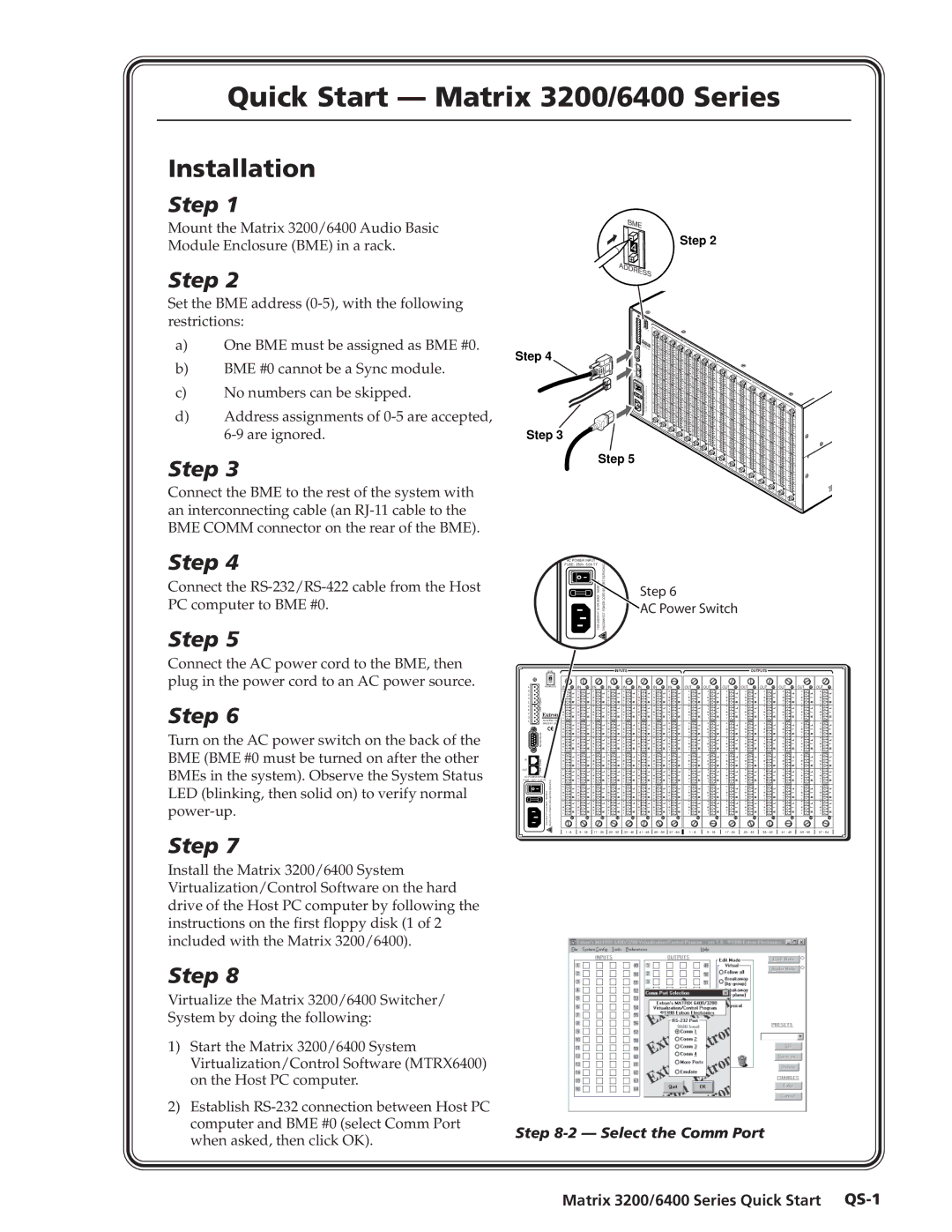
Matrix 3200/6400 Series Quick Start QS-1
Quick Start Matrix 3200/6400 Series
Matrix 3200/6400 Series Quick Start
Quick Start Matrix 3200/6400 Series, cont’d
Table of Contents
Table of Contents, cont’d
One
Matrix 3200/6400 Series Introduction
What is a Matrix 6400 Audio Switcher?
Features
Introductiontroduction, cont’d
Inputs Outputs
Feature Descriptions
Matrix 6400 Audio Switcher Specifications
Introduction, cont’d
Matrix 3200/6400 System Manuals
Audio input audio BME
Introduction, cont’d
Two
Introductionstallation, cont’d
Matrix 6400 Audio Switcher Installation
Installing the Matrix 6400 Audio BME
Matrix 3200/6400 Series Installation
Connecting the BME Comm interconnecting cables
Setting BME Addresses
Applying AC Power to the BMEs
Installation, cont’d
Connecting the RS-232/RS-422 Cable to BME #0
Connecting the AC Power Cables to the BMEs
Virtualizing the Matrix 3200/6400 Switcher/System
Using the Audio Captive Screw Connectors
Matrix 6400 Audio Input/Output Cabling
A Matrix 6400 Audio Switcher Stereo backplane
D Align the stereo audio connectors before plugging them
Installation, cont’d
Three
Matrix 3200/6400 Series Control Software
ControlSoftware,cont’d
Matrix 3200/6400 Series Control Software
Igure 3-3.A
Control Software, cont’d
Matrix 3200/6400 Series Control Software
A Main Screen Ties
How to Create Rooms within the Matrix 3200/6400 System
Igure 3-7.A
Matrix 3200/6400 Series Control Software
How to Program the Matrix 3200/6400 System in Emulate Mode
How to Save and Restore the Matrix 3200/6400 Settings
10.A
Four
Programmer’ser’sGuide,Guidecont’d
Serial Communications Port
Matrix 3200/6400 Series Programmer’s Guide
Command/Response Table
Host to Switcher Communications
Programmer’s Guide, cont’d
COMMAND/RESPONSE Table
ROOM# Name Virtual Outputs
VIRT-OUT# Name LVL1 LVL2 LVL6 Vmutamut
ØVI
Read RGB Delay for 1 ch Out Dly Set RGB Delay for 1 ch
Quick Recall Preset Rpr
Switcher Generated Unsolicited Responses
Five
Adding a Front Panel Controller to an existing system
UpgradesandandTroubleshooting,co t’d
Upgrade and Troubleshooting Procedures
Matrix 3200/6400 Series Upgrades and Troubleshooting
Matrix 6400 Audio BME Internal Access
Installing a Software Update
Upgrades and Troubleshooting, cont’d
Ribbon Cable Connectors
Swapping BME #0 RS-232 / RS-422 Ports
Swapping Serial Ports RS-232/RS-422
System Status
Troubleshooting a Matrix 3200/6400 System Problem
Power Supplies
Communications
Primary
A Inserting an audio card into slot
Matrix 6400 Audio Switcher Upgrade Changing the Matrix Size
Determining Audio Switcher Circuit Card Population
A Audio output card gain jumpers
Changing the Audio Output Card Gain Jumpers
Adding a Matrix 6400 Audio BME
Adding BMEs to a Matrix 3200/6400 System
Software Procedure Before and After a Hardware Upgrade
Upgrade System Software Procedure
Before Hardware Changes
After Hardware Changes
Upgrades and Troubleshooting, cont’d
AAppendix a
Reference Information
ReferenceInformation,c t’d
Matrix 3200/6400 Series Part Numbers
Matrix 3200/6400 Series Reference Information
Matrix 3200/6400 Series Part Numbers from previous
Extron Part Matrix 6400 Wideband Switcher Iofr
Related Part Numbers
BNC Cables Super High Resolution SHR BNC Cables
Reference Information, cont’d
Matrix 3200/6400 Series Part Numbers
Pre-cut Cables
Binary/Hex/Decimal Conversion Table
Glossary of terms
Matrix 3200/6400 Series Reference Information
Reference Information, cont’d
PCB Printed Circuit Board
Reference Information, cont’d
Matrix 3200/6400 Series Reference Information A-11
Virtual conference room See videoconferencing
Reference Information, cont’d
FCC Class a Notice Extron’s Warranty
Extron Electronics, USA