The following restrictions apply to installing BMEs:
•One BME must be assigned as BME #0.
•BME #0 cannot be a Sync module.
•Address assignments must not skip numbers.
•Address assignments of 0 - 5 are accepted, BMEs w/address
•A system is limited to one audio module.
•A system may NOT include both Wideband video and Low Resolution video modules.
2.Setting BME Addresses
Each BME must be set to a unique address of 0 - 5 using a pushbutton switch located on the rear panel (see Figure
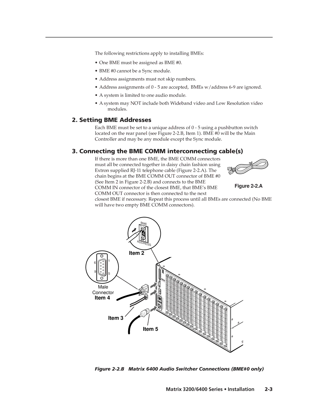
3. Connecting the BME COMM interconnecting cable(s)
If there is more than one BME, the BME COMM connectors must all be connected together in daisy chain fashion using Extron supplied
Figure 2-2.A
are connected (No BME
BME 4 ADDRESS
6
1
Item 2
9
5
Male
Connector
Item 4
Item 3
A |
|
| BME |
|
|
|
|
|
|
B |
|
|
|
|
|
|
|
|
|
C |
|
| 4 |
|
|
|
|
|
|
D |
|
| ADDRESS |
|
|
|
|
| |
A |
|
|
|
|
|
|
| ||
E |
| COMM. |
|
|
|
|
|
|
|
B |
|
|
| IN |
|
|
|
| |
C |
| MKP |
|
|
|
|
|
| |
D |
|
|
|
| IN | INPUTS |
|
| |
E |
|
|
|
|
|
|
| ||
|
|
| ANAHEIM, |
|
| IN |
|
| |
|
|
| CA |
|
|
|
|
| |
|
|
| MADE IN |
|
| IN |
|
| |
|
|
|
| USA |
|
|
|
| |
|
|
|
|
|
|
| IN |
|
|
|
|
|
|
|
|
| IN |
|
|
|
|
|
|
|
|
| IN |
|
|
IN |
|
|
|
|
|
| IN |
|
|
|
| COMM. |
|
|
|
| OUT |
| |
UT |
|
|
|
|
|
|
| ||
A |
| BME |
|
|
|
|
|
| OUT |
FUCPO | WER |
|
|
|
|
|
|
| |
SE: | INP |
|
|
|
|
|
| ||
250V |
|
|
|
|
|
|
| ||
|
| 5.0UT |
|
|
|
|
|
| |
|
| ATT |
|
|
|
|
|
| |
|
|
| 50/60Hz |
|
|
|
|
|
|
|
|
| 0.5A MAX |
|
|
|
|
|
|
|
|
|
|
|
|
|
|
| |
|
|
|
|
| 1 |
|
|
| |
|
|
|
|
|
| 9- |
|
|
|
|
|
|
|
|
| 16 |
|
|
|
|
|
|
|
|
| 17- |
|
|
|
|
|
|
|
|
| 24 | 25- |
|
|
|
|
|
|
|
|
|
|
| |
|
|
|
|
|
|
| 32 |
|
|
|
|
|
|
|
|
| 33- |
|
|
|
|
|
|
|
|
| 40 |
|
|
|
|
|
|
|
|
| 41- |
|
|
|
|
|
|
|
|
| 48 |
|
|
|
|
|
|
|
|
| 49- |
|
|
Item 5 |
|
|
|
|
|
| 56 |
|
|
|
|
|
|
|
| 57- | 64 | 8 | |
|
|
|
|
|
|
|
| 1- |
|
|
|
|
|
|
|
|
|
| 9- |
|
|
|
|
|
|
|
|
| 16 |
OUT![]()
![]()
![]() OUT
OUT![]()
OUTPUTS ![]() OUT
OUT![]()
32
![]() OUT
OUT![]()
![]()
![]() OUT
OUT![]()
![]()
![]()
![]()
![]()
![]() OUT
OUT![]()
![]()
![]()
![]()
![]()
![]()
![]()
Figure 2-2.B Matrix 6400 Audio Switcher Connections (BME#0 only)
Matrix 3200/6400 Series • Installation |