MVX Plus
VGA Matrix Switchers
Instrucciones de seguridad Español
Safety Instructions English
Consignes de Sécurité Français
Sicherheitsanleitungen Deutsch
MVX Plus 128 VGA Matrix Switchers Quick Start QS-1
Plug the switcher into a grounded AC source
Create a tie
Saing or recalling a preset
Viewing and adjusting the audio level
QS-2 MVX Plus 128 VGA Matrix Switchers Quick Start
Table of Contents
Table of Contents, cont’d
MVX Plus 128 VGA Matrix Switchers Table of Contents Iii
Iv MVX Plus 128 VGA Matrix Switchers Table of Contents
Appendix B Specifications, Part Numbers, Accessories
Vi MVX Plus 128 VGA Matrix Switchers Table of Contents
One
MVX Plus 128 VGA Matrix Switchers Introduction
About the Matrix Switchers
About this Manual
Definitions
Introduction, cont’d
Features
Tie any input to any or all outputs
Introduction, cont’d
Two
Video connections
Mounting the Switcher
MVX Plus 128 VGA Matrix Switchers Installation
Cabling and Rear Panel Views
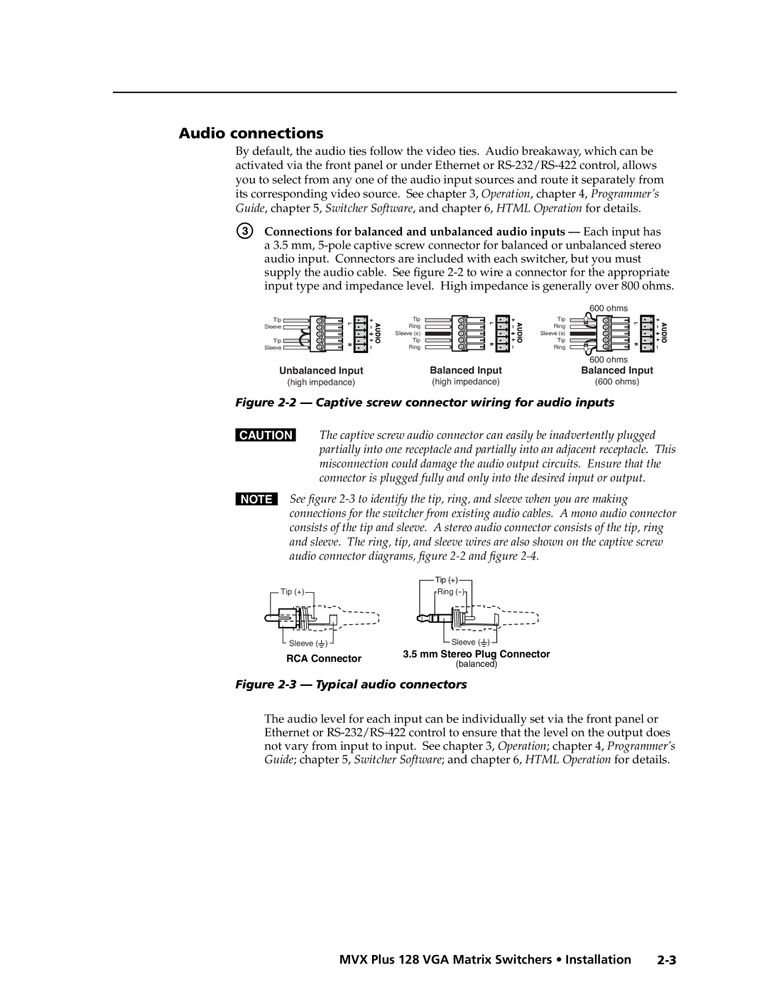
Audio connections
Captive screw connector wiring for audio inputs
RS-232/RS-422 connection
Installation, cont’d
Ethernet connection
To control the networked switcher with SIS commands from
Program or has downloaded Html pages from the switcher
Cabling and RJ-45 connector wiring
Power connection
Reset button
Three
MVX Plus 128 VGA Matrix Switchers Operation
Front Panel Controls and Indicators
Definitions
Control buttons
Input and output buttons
Operation, cont’d
Controls
Sample button icons
Button icons
Front Panel Operations
Power
Creating a configuration
Press and release the Esc button figure
Example 1 Creating a set of video and audio ties
Press and release the input 5 button figure
All input buttons and output buttons
Press and release the Enter button figure
Press and release the output 1 button figure
Example 2 Adding a tie to a set of video and audio ties
13 Press the Enter button
Press and release the output 4 button figure
Example 3 Removing a tie from a set of video and audio ties
Video
Current configuration figure 3-20 is now
Viewing a configuration
Rgbhv button and the Audio button figure
Lights red
Red
Press and release the Rgbhv button to deselect Rgbhv figure
27 I/O grouping of incompatible video formats
Grouping
Operation, cont’d
Press and release the Enter button to select group 1 figure
Example 5 Grouping inputs and outputs
32 Select an I/O group
Press and release the Preset button to select group 2 figure
Example 6 Setting the RGB delay for an output
Setting RGB delay
Press and release the output 17 button figure
35 Select RGB Delay mode
Press and release the Rgbhv button figure
Using presets
figure
Example 7 Saving a preset
Press and release the Preset button figure
Example 8 Recalling a preset
47 Press the Enter button
Muting and unmuting video and/or audio outputs
Release the Rgbhv button and the Audio button figure
Example 9 Muting and unmuting an output
50 Mute the outputs
Stops blinking
Viewing and adjusting the input audio level
To blink red, then release the button
Audio level
54 Clear all selections
Example 10 Viewing and adjusting an input audio level
Input audio level adjustment displays
3 F 4
Audio mode. The Audio button stops blinking
Viewing and adjusting the output volume
Audio volume
Press and release the Audio button figure
Reading the displayed volume
Audio volume adjustment settings
10 11
Example 11 Viewing and adjusting an output volume level
3 4 5 6 7 F 8 9 10 11
Performing a system reset from the front panel
Locking out the front panel Executive mode
66 Toggle background illumination on or off
Background illumination
Serial protocol
Selecting the RS-232/RS-422 protocol and baud rate
Rear Panel Controls
Performing soft system resets
70 Whole switcher and absolute resets
Optimizing the Audio
Performing a hard reset
If necessary, turn off power to the switcher
To the switcher figure
Configuration Worksheets
Troubleshooting
Worksheet example 1 System equipment
73 Worksheet example 2 Daily configuration
Worksheet example 2 Daily configuration
74 Worksheet example 3 Test configuration
Worksheet example 3 Test configuration
Configuration worksheet
Output destinations
Operation, cont’d
Four
RS-232/RS-422 Link
MVX Plus 128 VGA Matrix Switchers Programmer’s Guide
Ethernet Link
Default IP addresses
Switcher-Initiated Messages
Host-to-Switcher Instructions
Using the Command/Response Tables
Switcher Error Responses
Symbol definitions
Command/Response Table for SIS Commands
Description
Command Ascii command Response Additional
% G InX! AudX$
Value Output Attenuation Volume
EX11X12...X112O
EX*MR
EZG
EVM
EDF
X1-X2-X2
X5#
Command/Response Table for IP SIS Commands
Command/response table for IP SIS commands
Example Response description
Special Characters
Five
MVX Plus 128 VGA Matrix Switchers Matrix Software
Matrix Switchers Control Program
Installing the software
Ethernet protocol settings
Comm port selection window
Using the software
Matrix Software, cont’d
Extron Matrix Switcher+ Control Program window blank
Control program IP setting/options window
IP Settings/Options window
Extron Name/Descriptor field
Matrix IP Address field
Use Dhcp checkbox
Gateway IP address field
Subnet Mask field
Hardware Address field
Use Daylight Savings checkbox
Time local field
Sync Time to PC button
GMT offset field
User Password field
Administrator Password field
Mail Server IP Address field
Mail Server Password field
Mail Server Domain Name field
Mail Addressee fields
Miles Standish
Download. Note the folder to which you save the firmware file
Updating firmware
Run the executable *.exe file to decompress the firmware file
Uploading Html files
Windows menus
Windows buttons, drop boxes, and trashcan
File menu
Status window
Tools menu
10 Ties shown as lines
Preferences menu
11 Ties shown as crosspoints
Using the help system
Using emulation mode
Master-Reset selection
12 Extron’s Button-Label Generator window
Button-Label Generator Program
Html Operation
Download the Startup
Access the switcher using Html pages as follows
Password. Click the OK button
MVX Plus 128 VGA Matrix Switchers Html Operation
System Status
System Status
Dsvp
Html Operation, cont’d
System Configuration
System Configuration
IP Address field
IP Settings fields
Unit Name field
Dhcp radio buttons
Savings time feature
Date/Time Settings fields
Click the Submit button
Passwords
Passwords
Mail IP Address field
Email Settings
Domain Name field
Email address fields
Firmware Upgrade
File Management
Browse through your system and select the desired files
Set and View Ties
Upload your own files as follows
Click the Browse button
Creating a tie
RGB and Audio Settings
Click the desired gain or attenuation value
Changing the input gain and attenuation
Button until the desired input is visible
Click the desired input
Click the desired output
Muting and unmuting one or all outputs
Mute one or all outputs as follows
Button until the desired output is visible
Click the desired RGB delay
Changing the RGB delay
Click the desired output volume step value
Changing the output volume level
Number Output Steps Attenuation Volume
Saving a preset
Global Presets
Recalling a preset
Special Characters
AAppendix a
MVX Plus 128 VGA Matrix Switchers Ethernet Connection
Default address
Pinging to determine Extron IP address
MVX Plus 128 VGA Matrix Switchers Ethernet Connection A-3
Pinging to determine Web IP address
Telnet tips
Connecting as a Telnet client
Open
Set carriage return-line feed
MVX Plus 128 VGA Matrix Switchers Ethernet Connection A-5
Escape character and Esc key
Local echo
IP addresses and octets
Subnetting a Primer
Gateways
Local and remote devices
Determining whether devices are on the same subnet
MVX Plus 128 VGA Matrix Switchers Ethernet Connection A-7
Ethernet Connection, cont’d
AppendixBB
Specifications
Specifications, Part Numbers, Accessories
Audio
Specifications, Part Numbers, Accessories, cont’d
Adapters, power supplies, labels Part number
Part Numbers and Accessories
Accessories
Included parts Replacement part Number
Cables
Male-to-female VGA molded connector cables Part number
Male-to-female VGA backshell connector cables Part number
Male-to-male VGA molded connector cables Part number
Button Labels
Installing labels in the matrix switcher’s buttons
Specifications, Part Numbers, Accessories, cont’d
Button label blanks
Specifications, Part Numbers, Accessories, cont’d
Extron Electronics, Europe
FCC Class a Notice Extron’s Warranty
Extron Electronics, USA