Programmer’s Guide, cont’d
Command | Response |
| Description |
1VI | Jims_Lecture,GrpB |
| Read Preset 1 breakaway information (follow versus breakaway mode) |
|
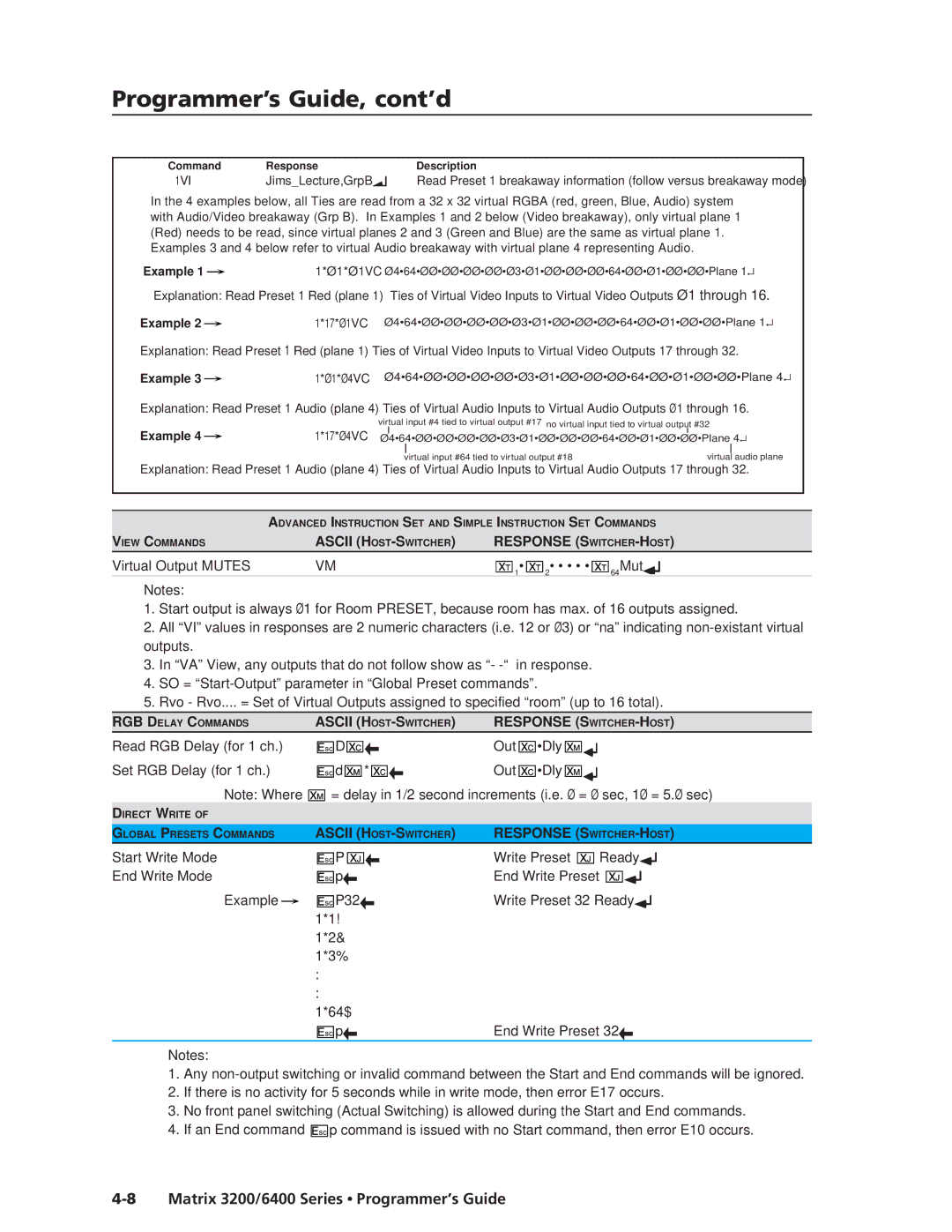
In the 4 examples below, all Ties are read from a 32 x 32 virtual RGBA (red, green, Blue, Audio) system with Audio/Video breakaway (Grp B). In Examples 1 and 2 below (Video breakaway), only virtual plane 1 (Red) needs to be read, since virtual planes 2 and 3 (Green and Blue) are the same as virtual plane 1. Examples 3 and 4 below refer to virtual Audio breakaway with virtual plane 4 representing Audio.
Example 1 |
| 1*Ø1*Ø1VC Ø4•64•ØØ•ØØ•ØØ•ØØ•Ø3•Ø1•ØØ•ØØ•ØØ•64•ØØ•Ø1•ØØ•ØØ•Plane 1↵ |
|
Explanation: Read Preset 1 Red (plane 1) Ties of Virtual Video Inputs to Virtual Video Outputs Ø1 through 16.
Example 2 |
| 1*17*Ø1VC Ø4•64•ØØ•ØØ•ØØ•ØØ•Ø3•Ø1•ØØ•ØØ•ØØ•64•ØØ•Ø1•ØØ•ØØ•Plane 1↵ |
|
Explanation: Read Preset 1 Red (plane 1) Ties of Virtual Video Inputs to Virtual Video Outputs 17 through 32.
Example 3 |
| 1*Ø1*Ø4VC Ø4•64•ØØ•ØØ•ØØ•ØØ•Ø3•Ø1•ØØ•ØØ•ØØ•64•ØØ•Ø1•ØØ•ØØ•Plane 4↵ |
|
Explanation: Read Preset 1 Audio (plane 4) Ties of Virtual Audio Inputs to Virtual Audio Outputs Ø1 through 16.
Example 4 |
| virtual input #4 tied to virtual output #17 no virtual input tied to virtual output #32 | ||||||||
| 1*17*Ø4VC |
| Ø4•64•ØØ•ØØ•ØØ•ØØ•Ø3•Ø1•ØØ•ØØ•ØØ•64•ØØ•Ø1•ØØ•ØØ•Plane |
|
|
| 4↵ | |||
|
| |||||||||
|
|
|
|
| ||||||
|
|
|
|
|
| virtual input #64 tied to virtual output #18 |
| virtual |
| audio plane |
|
|
|
|
|
| |||||
Explanation: Read Preset 1 Audio (plane 4) Ties of Virtual Audio Inputs to Virtual Audio Outputs 17 through 32.
| ADVANCED INSTRUCTION SET AND SIMPLE INSTRUCTION SET COMMANDS | ||||
|
|
|
|
|
|
VIEW COMMANDS | ASCII | RESPONSE | |||
Virtual Output MUTES | VM | 1• 2• • • • • 64Mut |
|
|
|
| |||||
|
|
| |||
Notes:
1.Start output is always Ø1 for Room PRESET, because room has max. of 16 outputs assigned.
2.All “VI” values in responses are 2 numeric characters (i.e. 12 or Ø3) or “na” indicating
3.In “VA” View, any outputs that do not follow show as “-
4.SO =
5.Rvo - Rvo.... = Set of Virtual Outputs assigned to specified “room” (up to 16 total).
RGB DELAY COMMANDS | ASCII | RESPONSE | |||
Read RGB Delay (for 1 ch.) | D | Out | •Dly |
|
|
| |||||
Set RGB Delay (for 1 ch.) | d * | Out | •Dly |
|
|
| |||||
Note: Where ![]() = delay in 1/2 second increments (i.e. Ø = Ø sec, 1Ø = 5.Ø sec)
= delay in 1/2 second increments (i.e. Ø = Ø sec, 1Ø = 5.Ø sec)
DIRECT WRITE OF
GLOBAL PRESETS COMMANDS |
| ASCII | RESPONSE | |||||||||
Start Write Mode |
| P | Write Preset | Ready |
|
|
| |||||
| ||||||||||||
End Write Mode |
| p | End Write Preset |
|
|
|
|
|
|
|
|
|
|
|
|
|
|
|
|
|
| ||||
Example |
| P32 | Write Preset 32 Ready |
|
|
| ||||||
|
| |||||||||||
| ||||||||||||
| 1*1! |
|
|
|
|
|
|
|
|
|
| |
| 1*2& |
|
|
|
|
|
|
|
|
|
| |
| 1*3% |
|
|
|
|
|
|
|
|
|
| |
| : |
|
|
|
|
|
|
|
|
|
| |
| : |
|
|
|
|
|
|
|
|
|
| |
| 1*64$ |
|
|
|
|
|
|
|
|
|
| |
|
| p | End Write Preset 32 | |||||||||
Notes:
1.Any
2.If there is no activity for 5 seconds while in write mode, then error E17 occurs.
3.No front panel switching (Actual Switching) is allowed during the Start and End commands.
4.If an End command ![]()
![]() p command is issued with no Start command, then error E10 occurs.
p command is issued with no Start command, then error E10 occurs.