INFORMATION COMMANDS | ASCII | RESPONSE |
|
|
|
|
|
|
|
|
|
| |||||||||||||
Request Information | I/i | I |
|
|
| X |
|
| •T |
|
| •U |
|
| •M |
|
|
|
|
|
|
|
| ||
|
|
|
|
|
|
|
|
|
|
|
|
|
|
|
|
| |||||||||
|
|
|
| X |
|
|
|
| •Vmt •Amt | •Sys | •Dgn |
|
|
|
|
|
| ||||||||
|
|
|
|
|
|
|
|
| |||||||||||||||||
Example |
|
| I | I64X64•T1•U2•M21X21•VmtØ•Amt1•Sys1•DgnØØ |
|
|
| ||||||||||||||||||
|
|
| |||||||||||||||||||||||
| |||||||||||||||||||||||||
Example explanation: I64X64 indicates that this BME has 64 physical inputs and 64 physical outputs. T1= Wideband Switcher, U2 indicates system has 2 BMEs and is set to M21X21 (21 Virtual Inputs and 21 Virtual Outputs). VmtØ = Video is not Muted, Amt1 = Audio is Muted. Sys1 indicates that this BME has no redundant power supply and the main power supply is on. DgnØØ indicates no error (BME’s self- test diagnostics passed. Dgn2Ø if reported = System physical size has changed since last virtualized.
Specific BME | I/i | Same as Request Information Response above. |
Notes: |
|
|
1.Command “ØI ” is equivalent to “I” or “i” command.
2.![]()
![]()
![]()
![]()
![]()
![]()
![]() 1 = Wideband, 2 =
1 = Wideband, 2 =
3.![]()
![]()
![]()
![]()
![]()
![]() +
+ ![]()
![]()
![]()
![]()
![]()
![]() is physical size of this BME.
is physical size of this BME.
4.![]()
![]()
![]()
![]()
![]()
![]() ,
, ![]()
![]()
![]()
![]()
![]()
![]() ,
, ![]()
![]()
![]()
![]()
![]()
![]()
![]() ,
, ![]()
![]()
![]()
![]()
![]()
![]()
![]() ,
, ![]()
![]()
![]()
![]()
![]()
![]()
![]()
![]() are each two digit fields.
are each two digit fields.
ADVANCED INSTRUCTION SET AND SIMPLE INSTRUCTION SET COMMANDS (PAGE 1 OF 3)
VIEW COMMANDS | ASCII | RESPONSE | ||||||||||||||||||||
Audio Gain | V/v | G | In ·Aud |
|
|
|
|
|
|
|
|
|
|
|
|
|
| |||||
| ||||||||||||||||||||||
Example |
| V15G |
|
|
|
|
|
|
|
|
|
|
|
|
|
|
| |||||
|
|
| ||||||||||||||||||||
|
| |||||||||||||||||||||
Example explanation: Virtual Input 15 Audio Level is set to | ||||||||||||||||||||||
Global PRESET information | VI |
|
|
| ,Grp |
|
|
|
|
|
|
|
|
|
|
| ||||||
|
|
|
| |||||||||||||||||||
Example |
| ØVI |
| Jims_Lecture,GrpA |
|
|
|
|
|
|
| |||||||||||
|
|
| ||||||||||||||||||||
|
| |||||||||||||||||||||
Global PRESET Ties | * | *ØØVA |
| SO• SO+1• SO+2 |
| • SO+15•All |
|
|
| |||||||||||||
|
|
|
|
|
| |||||||||||||||||
|
| |||||||||||||||||||||
|
|
|
|
|
|
|
| |||||||||||||||
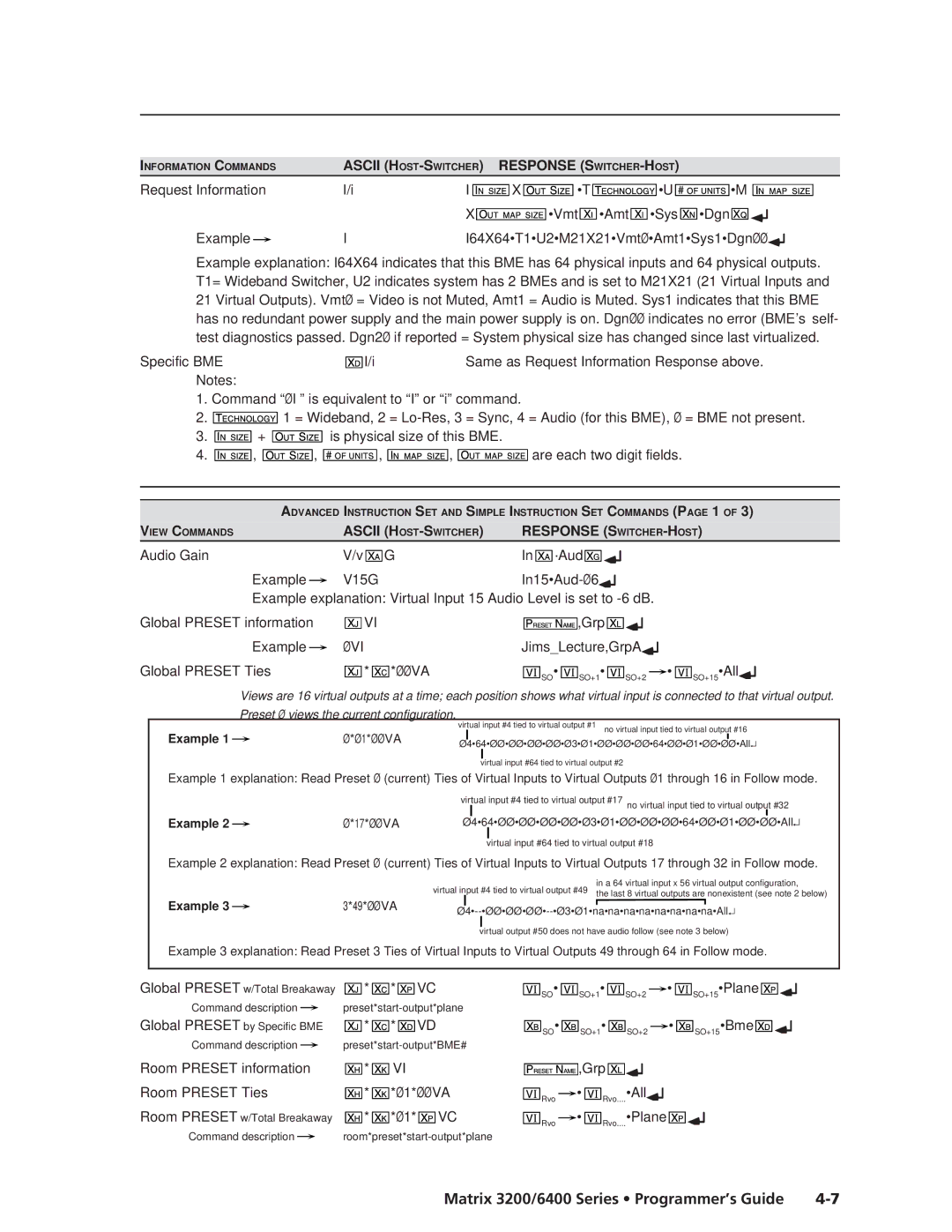
Views are 16 virtual outputs at a time; each position shows what virtual input is connected to that virtual output. Preset Ø views the current configuration.
virtual input #4 tied to virtual output #1
no virtual input tied to virtual output #16
Example 1 |
| Ø*Ø1*ØØVA |
|
|
| Ø4•64•ØØ•ØØ•ØØ•ØØ•Ø3•Ø1•ØØ•ØØ•ØØ•64•ØØ•Ø1•ØØ•ØØ•All↵ | |||
|
|
| ||
virtual input #64 tied to virtual output #2
Example 1 explanation: Read Preset Ø (current) Ties of Virtual Inputs to Virtual Outputs Ø1 through 16 in Follow mode.
virtual input #4 tied to virtual output #17 no virtual input tied to virtual output #32
Example 2 |
| Ø*17*ØØVA |
| Ø4•64•ØØ•ØØ•ØØ•ØØ•Ø3•Ø1•ØØ•ØØ•ØØ•64•ØØ•Ø1•ØØ•ØØ•All |
| ↵ |
| ||||||
|
|
|
|
|
|
|
virtual input #64 tied to virtual output #18
Example 2 explanation: Read Preset Ø (current) Ties of Virtual Inputs to Virtual Outputs 17 through 32 in Follow mode.
virtual input #4 tied to virtual output #49 | in a 64 virtual input x 56 virtual output configuration, | |
the last 8 virtual outputs are nonexistent (see note 2 below) | ||
|
Example 3 |
| 3*49*ØØVA | |||
| |||||
|
|
|
|
| virtual output #50 does not have audio follow (see note 3 below) |
|
|
|
| ||
Example 3 explanation: Read Preset 3 Ties of Virtual Inputs to Virtual Outputs 49 through 64 in Follow mode.
Global PRESET w/Total Breakaway | * | * | VC |
|
| SO• |
| SO+1• |
|
|
|
|
|
|
|
|
| • | SO+15•Plane | |||||||||
SO+2 | ||||||||||||||||||||||||||||
Command description |
|
|
|
|
|
|
|
|
|
|
|
|
|
|
|
|
|
|
|
|
|
|
|
| ||||
|
|
|
|
|
|
|
|
|
|
|
|
|
|
|
|
|
|
|
|
|
|
| ||||||
Global PRESET by Specific BME | * | * | VD |
|
| SO• |
| SO+1• |
|
|
|
|
|
|
|
| • | SO+15•Bme | ||||||||||
SO+2 | ||||||||||||||||||||||||||||
Command description |
|
|
|
|
|
|
|
|
|
|
|
|
|
|
|
|
|
|
|
|
|
|
|
| ||||
|
|
|
|
|
|
|
|
|
|
|
|
|
|
|
|
|
|
|
|
|
|
| ||||||
Room PRESET information | * | VI |
|
|
|
|
|
| ,Grp |
|
|
|
|
|
|
|
|
|
|
|
|
|
| |||||
|
|
|
|
|
|
|
|
|
|
|
|
|
|
|
|
|
|
|
| |||||||||
Room PRESET Ties | * | *Ø1*ØØVA |
|
|
|
| • | Rvo....•All |
|
|
|
|
|
|
|
| ||||||||||||
|
| Rvo |
|
|
|
|
|
|
|
| ||||||||||||||||||
Room PRESET w/Total Breakaway | * | *Ø1* | VC |
|
|
|
| • | Rvo....•Plane |
|
|
|
|
| ||||||||||||||
|
| Rvo |
|
|
|
|
| |||||||||||||||||||||
Command description |
|
|
|
|
|
|
|
|
|
|
|
|
|
|
|
|
|
|
|
|
|
|
| |||||
|
|
|
|
|
|
|
|
|
|
|
|
|
|
|
|
|
|
|
|
|
| |||||||
Matrix 3200/6400 Series • Programmer’s Guide |