Large Scale Matrix Switchers
CrossPoint 450 Plus Series MAV Plus series
Sicherheitsanleitungen Deutsch
Safety Instructions English
Consignes de Sécurité Français
Instrucciones de seguridad Español
FCC Class a Notice
Page
Table of Contents
Table of Contents, cont’d
Command/Response Table for IP-Specific SIS Commands
Table of Contents, cont’d
CrossPoint 450 Plus and MAV Plus Switchers Table of Contents
Table of Contents, cont’d
One
About this Manual
About the Matrix Switchers
CrossPoint 450 Plus and MAV Plus Switchers Introduction
CrossPoint 450 Plus / MAV Plus application
Introduction, cont’d
Features
Audio inputs audio BMEs only
Dsvp data display
Tie any input to any or all outputs
Introduction, cont’d
Two
Setup and Installation Checklist
Mounting the Switcher
Rear Panel Cabling and Features
Mounting instructions
Installation, cont’d
Video or sync input and output video and sync BMEs\⤀
Sync termination switches systems with sync BMEs\⤀
Audio input and output systems with audio BMEs\⤀
Typical audio connectors
Setting a BME address video BME shown
BME connection and selection
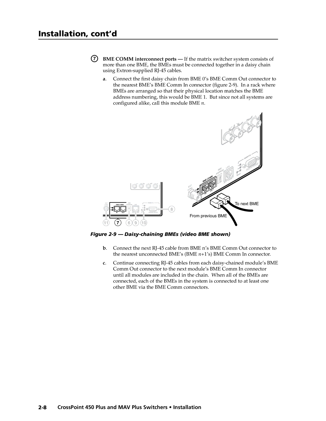
Daisy-chaining BMEs video BME shown
RS-232/RS-422
Remote
Cabling and RJ-45 connector wiring
Ethernet
Reset button
External sync systems with MAV Plus video BMEs\⤀
Power
BBG 6 a
Front Panel Configuration Port
Pin D
Installation, cont’d
Three
CrossPoint 450 Plus and MAV Plus Switchers Operation
Operation
Front Panel Controls and Indicators
C d e f g h
Operation, cont’d
Input and output buttons
Systems with CrossPoint 450 Plus Wideband switcher BMEs
Control buttons
CrossPoint 450 Plus and MAV Plus Switchers Operation
Operation, cont’d
Rgbhv Video
Power indicators
Primary and Redundant Power Supply LEDs
QS-FPC Front Panel Operations
Button labels
Definitions
Creating a configuration
Example 1 Creating a set of ties
Select an input Press and release the input 5 button
Input 5 video and audio tied To outputs 3, 4, Output
Example 2 Adding a tie to a set of ties
Press and release the Input 5 button
CrossPoint 450 Plus and MAV Plus Switchers Operation
Example 3 Removing a tie from a set of ties
Select the output Press and release the output 4 button
Confirm the change Press and release the Enter button
Viewing a configuration
49 50 51 52 53 54 55
17 18 19 20 21 22 23
Grouping
24 25
Press the Preset button to select group
Example 5 Grouping inputs and outputs
Group #
Setting RGB delay systems with wideband BMEs\⤀
Example 6 Setting the RGB delay for an output
3 4 5 6 7 8 9 17 18 19 20 21 22 23 24 25 26 NI
Using presets
Exit RGB Delay mode Press and release the Rgbhv button
Example 7 Saving a preset
Seconds
Example 8 Recalling a preset
4 5 6 7 8 17 18 19 20 21 22 23 24 NI
Muting and unmuting outputs
Example 9 Muting and unmuting an output
Mute outputs one at a time
View button returns to unlit or background illumination
Audio gain and attenuation
Example 10 Viewing and adjusting an input audio level
4 5 6 7 8 9 17 18 19 20 21 22 23
Lower the volume
Reading the displayed volume
Audio volume adjustment settings
Example 11 Viewing and adjusting an output volume level
Select an output Press and release the Output 1 button
10 11 12 13 23 24 25 26 27 28 29 39 40 41 42 43 44 45
Setting the front panel locks Executive modes\⤀
Selecting Lock mode 2 or toggling between mode 2 and mode
Performing a system reset from the front panel
Power
Background illumination
Selecting the rear panel Remote port protocol and baud rate
Serial protocol
Reset Mode Comparison/Summary
Rear Panel Operations
Performing soft system resets reset modes 3, 4, and 5\⤀
Reset times
Performing a hard reset reset mode
Optimizing the Audio Systems with Audio BMEs
General checks
Troubleshooting
Configuration Worksheets
Worksheet example 1 System equipment
Input sources
Worksheet example 2 Daily configuration
Worksheet example 2 Daily configuration
Worksheet example 3 Test configuration
Worksheet example 3 Test configuration
Operation, cont’d
Blank configuration worksheet
Preset #
Operation, cont’d
Four
Serial Ports
Rear panel Remote port
Front panel Configuration port
Optional 9-pin TRS RS-232 cable
Ethernet connection
Default IP addresses
Ethernet LAN\⤀ Port
Establishing a connection
Connection Timeouts
Using Verbose Mode
Number of connections
Host-to-Switcher Instructions
Switcher-Initiated Messages
Switcher Error Responses
Using the Command/Response Tables
X1 =
Command/response table for SIS commands
Symbol definitions
X2! =
@ %
Command Ascii command Response Additional
+QX!*X@!...X!*X@! Qik
Description
$+G
$*X%G
$*X&g
$-G
@+V
@-V
Audio mute commands
X1@
EX1,X@1,X@2, ... X@nMR
EX *X@ *1VC
$ G
X1# 1 , X1# 2 , ... X1# n
View ties, gain, volume, mutes, and presets \⤀
EX1& 1X1& 2 ...X1& n O
0 0 0 4 1 1 2 2 1 2 2 3 3 3 3 2 1 2 2 3 3 3
EX1,X1@NP
EX1,X1!NR NmrX1,X1
EX1*X1@,X1!NP NmpX1*X1@,X1
EX1 ZR
EX1 *X1@ ZP
X2 -X2
Information requests \ ⤀
EDF
Command/Response Table for IP-Specific SIS Commands
IpzX3$
IptX3@
X3#
X3%
Special Characters
Programmer’s Guide, cont’d
Five
CrossPoint 450 Plus and MAV Plus Switchers Matrix Software
Matrix Switchers Control Program
Installing the software
Ethernet protocol settings
Software operation via Ethernet
Using the Matrix Switcher Control software
Matrix Software, cont’d
Address and password entry
Extron Matrix Switchers Control Program window
Sample program window, with ties and icons
IP Settings/Options window
Control program IP Setting/Options window
Use Dhcp check box
Address and Name fields
Hardware Address field
Date, Time local\⤀, and GMT offset\⤀ fields
Use Daylight Saving check box
Administrator Password and User Password fields
Sync Time to PC button
Miles Standish
Mail Addressee fields
Location of firmware upgrade files
Updating firmware
Downloading firmware upgrade files
10. See Ethernet-connected firmware upload, below
Ethernet-connected firmware upload
Serial-port-connected firmware upload
11 Add Device window
13 Choose Firmware File window
Uploading Html files
15 Html Files List window
File menu
Windows buttons, drop boxes, and trash can
Windows menus
Tools menu
16 Status window
Preferences menu
17 Ties shown as crosspoints
Master-Reset selection
Using Emulation mode
Using the help system
Installing the Button Label Generator software
Button Label Generator Program
Using the Button Label Generator software
20 Button Label Generator window
Six
CrossPoint 450 Plus and MAV Plus Switchers Html Operation
Downloading the Startup
Status Tab
System Status
Html Operation, cont’d
Dsvp page systems with a sync BME only\⤀
Configuration Tab
System Settings
Dhcp radio buttons
IP Settings fields
Unit Name field
IP Address field
Date/Time Settings fields
Date/Time Settings fields
Passwords
Passwords
Domain Name field
Email Settings
Mail IP Address field
Firmware Upgrade
Email address fields
Click the Browse button. a Choose File window appears
File Management Tab
File Management
Control Tab
Set and View Ties
Creating or deleting a tie
Rgbhv and Audio Settings
12 RGB and Audio Settings
13 Input selection drop box
Mute and unmute one or all outputs
15 Output selection drop box
17 Output selection drop box
Change the output volume level audio models\⤀
19 Output selection drop box
Number Output Steps Attenuation Volume
Global Presets
Saving a preset
Recalling a preset
AppendixAA
Pinging to determine the Extron IP address
Default IP address
Ethernet Link
Pinging to determine the Web IP address
Ethernet Connection, cont’d
Open
Connecting as a Telnet client
Telnet tips
Set carriage return line feed
Escape character and Esc key
Local echo
Close
Local and remote devices
Subnetting a Primer
Gateways
IP addresses and octets
Determining whether devices are on the same subnet
Example
AppendixBB
CrossPoint 450 Plus Specifications
Reference Information
Control/remote switcher
MAV Plus Specifications
Reference Information, cont’d
Audio input audio BMEs
EMI/EMC
Model Part number
Part Numbers and Accessories
CrossPoint 450 Plus system part numbers
MAV Plus system part numbers
BME part numbers
Order all BMEs of the same matrix size, such as
MAV Plus video BMEs
CrossPoint 450 Plus wideband video BMEs
CrossPoint 450 Plus sync BMEs
Replacement parts
Included parts
Bulk cable RG6 super high resolution cable Part number
Optional accessories
Accessory Part number
RG59 high resolution cable Part number
MHR mini high resolution cable Part number
Removing and Installing Button Labels
Installing labels in the matrix switcher’s buttons
Button label blanks
Reference Information, cont’d
Extron Warranty
Extron USA West