Manuals
/
FIC
/
Computer Equipment
/
Laptop
FIC
A360 Removing the LCD Panel, Two screws of LCD panel connector, Maintenance & Disassembly
Models:
A360
1
129
187
187
Download
187 pages
205 b
126
127
128
129
130
131
132
133
Page 129
Image 129
Page 128
Page 130
Page 129
Image 129
Page 128
Page 130
Contents
FIC A360 Intel FC-PGA Pentium-III /Celeron Notebooks
A360 Model Reference and Service Manual
Legal Notice
How to Contact FIC Portable Computing Group
Copyright 2001 FIC, Inc ALL RIGHTS RESERVED - Printed in Taiwan
Reference and Service Manual
July 2001, Volume
F I C A 3 6 0 M O D E L
Contents
Preface
Intended Audience
Table of Contents
Chapter 2 Installation and Upgrade
Preface Chapter 1 Outline of the A360
Chapter 3 Software Functional Overview
Table of Contents
3.3.16 Intel PIIX4M GPO Signal 3.3.17 PMU07 GPIO Signal
Chapter 4 Hardware Functional Overview
Chapter 6 Troubleshooting and Repair
Chapter 5 Maintenance & Disassembly
Appendix A Notebook Specification
Appendix B Pin Assignments
Appendix C FRU Parts Listing
1.1 Introduction
1.2 Feature Highlights
Outline of the A360
Chapter1
CD-ROM
Outline of the A360
DVD-ROM
CD-RW
Power
Power System
LED Indicator
Management
1.3 System Configuration
BlueTooth
Audio DJ OZ168
1.4 Quick Tour of the Notebook
1.4.1 Inside the Notebook
Color LCD Display Panel
Easy Buttons
Glide Pad Pointing Device
Power Button
Status LED Panel
Power Status LED Indicator
o /q
Keyboard Panel
Function
Hot Key
Handler
Fn + F12
Cover Switch
Lock On / Off Switch
1.4.2 Front Side of the Notebook
Woofer
1.4.3 The Right Side of the Notebook
BlueTooth LED
Audio-DJ Display
Forward Button
IR Port
Thumb-Wheel Volume Control
Headphone Jack
Microphone Jack
PS/2 Port
1.4.4 The Left Side of the Notebook
Air Inhalant
Locking Device Keyhole
1.4.5 The Rear Side of the Notebook
AC Power Port
Printer Port LPT1
TV-Out Port
LAN Port
Series Port COM
Modem Port
IEEE1394 Port
Battery Bay
Battery Release Latch
1.4.6 The Under Side of the Notebook
Tilt Foot Left and Right
1.5.1 AC Adapter and Power Cord
1.5 Notebook Accessories and System Options
1.5.2 Battery Pack
1.5.3 Internal Modem Module
1.6 System BIOS SETUP Program
1.5.7 Audio-DJ
1.5.8 Blue Tooth Module
Figure 1-13 BIOS Setup Main Menu
1.6.1 Using the Main Menu
Boot
Advanced
1.44/1.25MB 3½”
Internal HDD/CD-ROM Sub-Menu
Internal HDD Sub-Menu
Auto
− /+
Figure 1-15 BIOS Setup Advanced Menu
1.6.2 Using the Advanced Menu
PhoenixBIOS Setup
Enabled
„ LCD Panel View Expansion
„ Silent Boot - Select boot screen during POST
Disabled / Enabled
1.6.3 Using the Security Menu
Figure 1-18 BIOS Setup Boot Menu
1.6.4 Using the Boot Menu
1.6.5 How to Exit the Setup Program
Chapter
Installation and Upgrade
2.1 Overview
2.2 Notebook Drivers and Utilities
2.2.2 Installing Windows 98 / Me / 2000 from CD / DVD ROM
Installation and Upgrade
Installing Windows 98 / Me from CD-ROM / DVD-ROM
Installing Windows 2000 from CD-ROM / DVD-ROM
Installing VGA Driver for Windows
2.2.3 Installing the VGA Device Driver
Installing VGA Driver for Windows Me
5. Select Search for a suitable driver for my device, and click Next
2.2.4 Installing the Audio Device Driver
Installing Audio Driver for Windows
Installing Audio Driver for Windows Me
2.2.6 Installing PCMCIA Driver
2.2.5 Installing Touch Pad Driver
2.2.7 Installing Twister Driver
Installing Touch Pad Driver for Windows 98 / Me
2.2.8 Installing Internal Modem Device Driver
Installing Internal Modem for Windows 98 / Me
Cable
Installing Internal LAN for Windows
2.2.9 Installing Internal LAN Device Driver
Installing Internal LAN for Windows Me
3. Select Specify the location of the driver, and click Next
Installing Modem Driver of Combo Device for Windows 98 / Me
2.2.10 Installing Internal Modem and LAN Combo Device Driver
Installing LAN Driver of Combo Device for Windows Me
Installing LAN Driver of Combo Device for Windows
2.2.12 Installing EzMail Driver
2.2.11 Installing Easy Button Driver
2.2.13 Enabling DMA Channel for Best Performance
Installing Easy Button driver for Windows 98 / Me
Æ System Æ Hardware Æ Device Manager
Enabling DMA channel for Windows
2.3.1 Jumper Settings
2.3 System Upgrades
Password Override CMOS / RTC Data Jumper Setting
Keyboard Type Select
2.3.2 CPU Upgrade Procedure
Keyboard Cover Bend Up
How to Access the CPU Socket
CPU Protective Tooling
screws
Figure 2-5 Remove heat sink plate
Remove CPU
Using the Memory Slot inside the Memory Compartment
2.3.3 Memory Upgrade Procedure
30 degrees
2.3.4 Hard Disk Upgrade Procedure
Figure 2-9 Remove Palm Reset
Figure 2-8 Insert Memory Module
7. Place back the palm rest and secure those screws
BIOS Version 1.0A-0004-3430
2.3.5 System BIOS Upgrade Procedure
3.2 Summary of the BIOS Specification
3.1 Overview
Software Functional Overview
Software Functional Overview
3.3.1 Key Chipset Summary
3.3 Subsystem Software Functions
3.3.2 System Memory
Expansion SO-DIMM
Pixel Resolution
3.3.3 Video
Supported Video Mode
Panel Type Initialization
Memory Model
VESA Mode
Refresh Rates In
Minimum
Panel TypeInitialization
VT82C686B GPI Pins
LCD Panel ID pin Definition
Panel Type
3.3.5 Audio
3.3.4 Enhanced IDE
3.3.6 Super I/O
3.3.7 PCMCIA
Indicator
3.3.8 LED Indicator
IDE accessing LED
FDD accessing LED
3.3.9-1 Port Replicator
3.3.9 Hot Keys Definition
Hot Key
Function
Device
3.3.10 Plug & Play
Connect
Resources
3-11
3.3.11 PCI Device
IDSEL Pin
Function
3.3.13 Resource Allocation
3.3.12 SMBus Devices
BIOS Need to Initialization
SMBus Device
DMA Channel
ISA DMAMap
Memory Map
Address Range
VT82C686BGPI pinassignment
3.3.14 GPIO Pin Assignment
Pin Name
Function Name
3-15
3.3.15 VT82C686B GPO pin assignment
3.3.17 M38867 GPIO pin assignment
3.3.16 PMU07 GPIO pin assignment
Function
Connected
3.4.2 System Power Plane
3.4 Power Management
3.4.1 General Requirements
Power
3.5.1 General Requirements
3.5 ACPI
Global System State Definitions
G0/S0 - Working
Sleeping State Definitions
3.5.2 System Power Plane
S1 Sleeping State
S2 Sleeping State
3.5.3 Global System State Definitions
3.5.4 Device Power State Definitions
G0/S0 - Working
G1 - Sleeping
S1 Sleeping State
3.5.5 Sleeping State Definitions
S3 Sleeping State STR mode
S2 Sleeping State
S4 Sleeping State STD mode
S5 Soft Off State
3.5.7 Power States transition event
3.5.6 Power Management Mode Transition Flow Chart
S1 Sleeping S2 Sleeping
G2 S5
3.5.9 Power Button and Internet / Mail Button
3.5.8 Lid Switch
3.5.10 Device Power Control Methodology
Power States
Power Down Controlled
Device Power control Methodology During S2 Mode
Device Power Control Methodology During S1 Mode
EC PMU07
3.5.11 Expanding Event Through the Embedded Controller
VT82C686B
SCI Source and GPE Event from PMU07
Control Method Battery Subsystem
3.5.12 Thermal Control
Resetting Cooling Temperatures from the User Interface
Active, Passive, and Critical Policies
Dynamically Changing Cooling Temperatures
Resetting Cooling Temperatures to Implement Hysteresis
3.5.13 Hardware Thermal Events
3.5.14 Active Cooling Strength
SCI Events
3.5.16 Critical Shutdown
3.5.15 Passive Cooling Equation
3.5.17 Other Implementation Of Thermal Controllable Devices
3.5.18 Thermal Control Methods
Figure 3-5 Other Thermal Control
Software Functional Overview
Software Functional Overview
3.5.19 AC Adapters and Power Source Objects
3.6 Battery Management
3.6.1 Battery Sub-system
3.6.2 Battery Low Warning
3.7 PMU07
3.6.4 AC Adapter
3.7.1 The System EC RAM with PMU07
3-38
updates the data periodically, or PMU detects the status change
3.7.2 PMU07 EC RAM List
3-39
The register type is word
Same as 1 st Battery CMBatt Data
3-41
STSX
3-42
data
STSX STSX AND Written
Should be
3-43
This register’s response time is 150usec max
Logic
edge
3-45
3-46
3.9 CMOS Setup Utility
3.8 Miscellaneous
3.8.1 Security
Hardware Functional Overview Chapter4
4.1 Overview
Hardware Functional Overview
4.2 System Hardware Block Diagram
Intel
DCIN
4.4.1 Intel Pentium-III Features
4.3 Chipset Summary
4.4 System Processor CPU
4.4.2 Intel Celeron Features
4.5 System Core Logic
4.5.1 VIA TWISTER Features
Define Integrated Solutions for Value PC Mobile Designs
High Performance CPU Interface
Advanced System Power Management Support
3D Rendering Features
Integrated Savage4 2D/3D/Video Accelerator
Motion Video Architecture
Inter-operable with VIA and other Host-to-PCI Bridges
4.5.2 VT82C686B Features
PCI to ISA Bridge
UltraDMA-33 / 66 / 100 Master Mode PCI EIDE Controller
Sophisticated PC99-Compatible Mobile Power Management
Universal Serial Bus Controller
System Management Bus Interface
4.7 Cache Memory
4.6 Clock Frequency Generator
4.8 System Memory
Plug and Play Controller
4.10 Video Subsystem
4.9 System BIOS
4.8.1 System Memory
4.8.2 Video Memory
4.11 PCMCIA Controller
4.10.2 Video Clock
CARDBUS CONTROLLERS
Supports 2 PCMCIA 2.1 and JEIDA 4.2 R2 cards or 2 CardBus cards
4.13 Keyboard and Pointing Device
4.12 Audio Subsystem
4.15.1 AC Power Adapter
4.15 Power Subsystem
4.15.2 Internal Battery Pack
4.14 Disk Drives Subsystem
4.15.3 DC-DC Module of Motherboard
4.15.4 LCD Inverter Board Assembly
4.16 Micro-P Subsystem PMU-07
5.2 Preventive Maintenance
Maintenance & Disassembly
5.2.1 Cleaning the Computer
5.1 Introduction
Maintenance & Disassembly
5.2.5 Handling the Computer Battery Packs
5.2.4 Maintaining the Hard Disk Drive
5.4 Notebook Field-Replaceable Parts and Assemblies
5.3 Required Tools and Equipment
5.4.2 System Unit Assembly
5.4.1 Cover-Display LCD assembly
LCD Power Inverter Board
Glidepad Touch Pad Module Assembly
Battery Pack
Keyboard Cover Assembly
CD-ROM / DVD-ROM / CD-RW Drive Assembly
Floppy Disk Drive Assembly
5.5.1 Removing the Battery Pack
5.5 Parts Removal and Replacement Procedures
5.5.2 Removing the Keyboard
System Base Unit Case
5.5.3 Removing the Palm Rest and Glide Pad
Palm-rest panel/cover Connectors
5.5.4 Removing the Internal Hard Disk Drive
Glidepad module
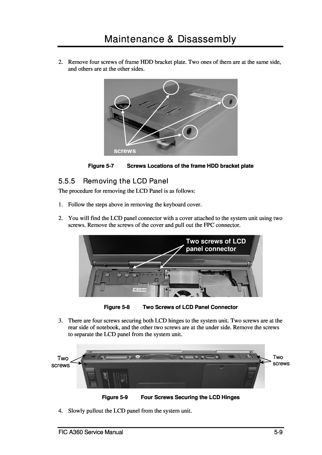
5.5.5 Removing the LCD Panel
Two screws of LCD panel connector
Six Screws Hinges
5.5.6 Removing the Heat Sink Plate
5.5.7 Removing the CPU
5.5.8 Removing the CD-ROM Module
Figure 5-12 Remove CPU
5.5.9 Removing the Top Cover and System Cover
Ten Screws
Push and slide CD-ROM
Two Hex Bolts Screws
5.5.10 Removing the Internal Speakers
Internal
Speaker
Screws
5.5.11 Removing the FDD Module
Hex bolts Lid Switch Screws
5.5.12 Removing / Replacing the Motherboard
Six Hex bolts at Rear Side of Notebook
6.2 System BIOS Related Problems
Troubleshooting & Repair
6.1 Introduction
6.1.1 Helpful Starters
Troubleshooting and Repair
POST Error Messages
Table 6-1a
value , read hex-value
Table 6-1b
6.2.2 Informational Messages
6.2.3 Beep Codes
Explanation of test terms for beep code table
Table 6-3 a BIOS Beep Codes
Beep codes for system board errors
Table 6-3 b BIOS Beep Codes
Table 6-3 c BIOS Beep Codes
Table 6-3 d BIOS Beep Codes
6.2.4 Run-time Error Messages
BIOS Run-time Error Messages
interrupt at address . Type
Table 6-5 a Quick Troubleshooting
6.3 Quick Troubleshooting
6-11
Table 6-5 b Quick Troubleshooting
Table 6-5 c Quick Troubleshooting
6.4 Component-Level Troubleshooting
6.4.1 General Overview
6-13
6.4.3 Memory Interface Check
6.4.2 Starting Check
Starting Check
Figure 6-2 Memory Interface Check
6.4.4 CRT Interface Check
6.4.5 FDD Interface Check
6-15
6.4.7 Internal Keyboard Check
6.4.6 HDD Interface Check
Figure 6-5 HDD Interface Check
Figure 6-6 Internal Keyboard Check
6.4.8 Glidepad Interface Check
6.4.9 CD-ROM Interface Check
6-17
6.4.11 Serial Port Interface Check
6.4.10 Charger Board Interface Check
Figure 6-9 Charger Board Interface Check
Figure 6-10 Serial Port Interface Check
6.4.12 External Keyboard Check
6.4.13 PS/2 Mouse Interface Check
6-19
6.4.15 Audio Port Interface Check
6.4.14 Printer Port Interface Check
Figure 6-13 Printer Port Interface Check
Figure 6-14 Audio Port Interface Check
6.4.16 PCMCIA Interface Check
6.4.17 USB Port Interface Check
6-21
6.4.19 LCD Panel Interface Check
6.4.18 DC-DC Power Check
Figure 6-17 DC-DC Power Check
Figure 6-18 LCD Panel Interface Check
6.4.20 Suspend Function Check
6-23
Figure 6-19 Suspend Function Check
Figure 6-20 Suspend Function Check
6.4.21 LED Indicator Function Check
6.4.22 Cover Switch Function Check
6.4.23 Internal Modem or LAN Port Check
6-25
6.4.25 SIR Interface Check
6.4.24 Internal Combo Modem / LAN Port Check
Figure 6-23 Internal Combo Modem / LAN Port Check
Figure 6-24 SIR Interface Check
6.4.26 IEEE1394 Interface Check
6.4.27 TV-Out Interface Check
6-27
A.1 System Specification
Notebook Specification
ppendix
MICRO PROCESSOR
BIOS ROM
Notebook Specification
VIDEO SUBSYSTEM
I/O SUBSYSTEM
STATUS LED INDICATORS
POWER MANAGEMENT UNIT PMU
SOUND SUBSYSTEM
POINTING DEVICE SUBSYSTEM
HOT-KEY DEFINITION
A.2 Display Specification
12.1” SVGA TFT LCD HANNSTAR
12.1” SVGA TFT LCD ADI
13.3” XGA TFT LCD UNIPAC
14.1” XGA TFT LCD HANNSTAR
14.1” XGA TFT LCD CPT
A.3 Floppy Disk Drive Specification
CITIZEN X1DE-32R
NEC FD-2238T-220
A.4 CD-ROM Drive Specification
QSI SCR-242 CAA8
MKE CR-177-DPK
A.6 CD-RW Drive Specification
A.5 DVD-ROM Drive Specification
MKE SR-8175-CPK
QSI SDR-081 EFAA
Keyboard Specification
Touch Pad Specification
Internal Modem Specification
A.11 Power Supply
A.10 Internal LAN Specification
AC POWER ADAPTER LITEON
A-10
A.13 DC/DC Specification
A.12 Inverter Specification
NICKEL-METAL HYDRIDE NI-MH BATTERY PACK
LITHIUM ION LI-ION BATTERY PACK
A.16 Environmental Requirements
A.14 Charger Specification
A.15 Mechanical Specification
LITHIUM ION LI-ION BATTERY PACK
Pin Assignments
CRT VGA Connector
AppendixB
FIC A550 Service Manual
B.2 Serial Port Connector
B.3 Parallel Port Connector
Pin Assignments
This high active output from the printer indicates that it
Bit 4 of the printer status register read the SLCT input
A low on this input from the printer indicates that there
B.5 USB Connector
B.4 PS/2 Mouse / Ext. Keyboard Mini-DIN Connector
B.6 CD-ROM IDE Connector
Following is the pin assignment of the PS/2 connector
B.7 DC-IN Jack Pin Assignment
B.8 LCD Connector Pin Assignment
The pin assignment of the DC-IN connector is as follows
The pin assignment of the LCD connector is as follows
B.10 HDD Pin Assignment
B.9 FDD Connector
The pin assignment for the FDD connector is as follows
The pin assignment of the internal HDD is as follows
B.12 Battery Connector
B.11 Internal Keyboard FPC Connector
The pin assignment of the internal keyboard connector is as follows
The pin assignment for the battery connector is as follows
B.13 Audio Jack
B.14 Internal Microphone Connector
SPDIF & Headphone Jack
Line-In Jack
FRU Parts Listing
AppendixC
FIC Part Number
FRU Parts Listing
FIC A460Series Service Manual
FIC Part Number
FRU Parts Listing
FIC Part Number
FRU Parts Listing
Top
Page
Image
Contents