Local Operation 4
Tutorial
Tutorial
To begin the tutorial, first verify that the Calibrator is
gld04.bmp
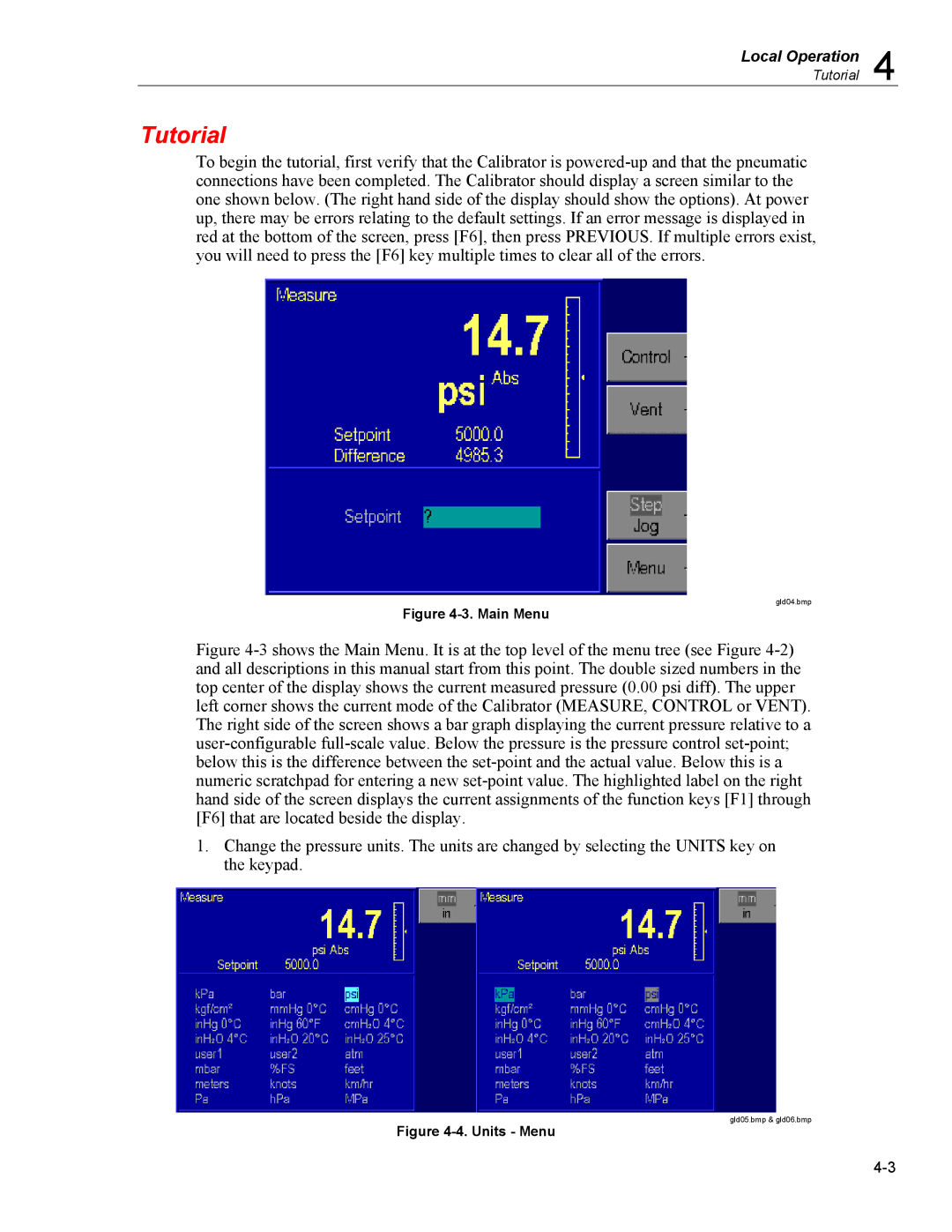
Figure 4-3. Main Menu
Figure 4-3 shows the Main Menu. It is at the top level of the menu tree (see Figure 4-2) and all descriptions in this manual start from this point. The double sized numbers in the top center of the display shows the current measured pressure (0.00 psi diff). The upper left corner shows the current mode of the Calibrator (MEASURE, CONTROL or VENT). The right side of the screen shows a bar graph displaying the current pressure relative to a user-configurable full-scale value. Below the pressure is the pressure control set-point; below this is the difference between the set-point and the actual value. Below this is a numeric scratchpad for entering a new set-point value. The highlighted label on the right hand side of the screen displays the current assignments of the function keys [F1] through [F6] that are located beside the display.
1.Change the pressure units. The units are changed by selecting the UNITS key on the keypad.
gld05.bmp & gld06.bmp