RUSKA 7350
Users Manual
76xx Interface Board
This board interfaces and conditions the pump position signal. The board interfaces these signals between the electronic and pneumatic module. This board also provides a 0 – 10 VDC signal to 0 – 100 psi electronic pneumatic regulators and the motor controller.
Pneumatic Module
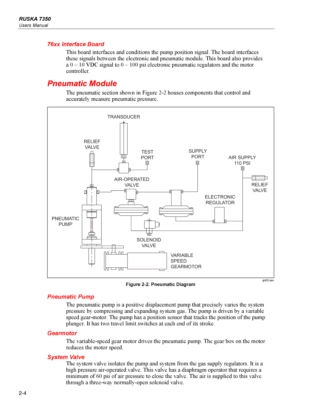
The pneumatic section shown in Figure
TRANSDUCER |
|
|
RELIEF |
|
|
VALVE | SUPPLY | |
TEST | ||
PORT | PORT | AIR SUPPLY |
|
| 110 PSI |
| RELIEF | |
VALVE |
| |
|
| VALVE |
|
| ELECTRONIC |
|
| REGULATOR |
PNEUMATIC |
|
|
PUMP |
|
|
SOLENOID |
|
|
VALVE |
|
|
| VARIABLE |
|
| SPEED |
|
| GEARMOTOR |
|
|
| gld02.eps |
Figure 2-2. Pneumatic Diagram
Pneumatic Pump
The pneumatic pump is a positive displacement pump that precisely varies the system pressure by compressing and expanding system gas. The pump is driven by a variable speed
Gearmotor
The
System Valve
The system valve isolates the pump and system from the gas supply regulators. It is a high pressure