Model 90100
Operators Manual
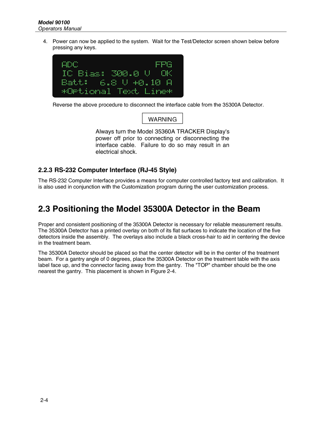
4.Power can now be applied to the system. Wait for the Test/Detector screen shown below before pressing any keys.
Reverse the above procedure to disconnect the interface cable from the 35300A Detector.
WARNING
Always turn the Model 35360A TRACKER Display's power off prior to connecting or disconnecting the interface cable. Failure to do so may result in an electrical shock.
2.2.3 RS-232 Computer Interface (RJ-45 Style)
The
2.3 Positioning the Model 35300A Detector in the Beam
Proper and consistent positioning of the 35300A Detector is necessary for reliable measurement results. The 35300A Detector has a printed overlay on both of its flat surfaces to indicate the location of the five detectors inside the assembly. The overlays also include a black
The 35300A Detector should be placed so that the center detector will be in the center of the treatment beam. For a gantry angle of 0 degrees, place the 35300A Detector on the treatment table with the axis label face up, and the connector facing away from the gantry. The "TOP" chamber should be the one nearest the gantry. This placement is shown in Figure