Model 90100
Operators Manual
3.2.6 Serial Communications Port
A computer interface has been provided in the form of a DCE configured
3.2.7 Electrometer
This block contains a fully guarded, five channel, single range, dual measurement mode electrometer. It is capable of providing both dose and dose rate measurements from the five detector channels. The connection to the electrometer's inputs is made through five coaxial inserts in a
The measurement mode is
3.2.8 Multiplexer and A/D Converter
This block consists of an six channel analog multiplexer and 16 bit A/D Converter which operates under the direct control of the microcontroller. Its main function is to convert the five analog voltage signals produced by the Electrometer Block into digital signals for use by the microcontroller. It is also used to measure the output of the 300 Volt Electronic Bias Supply. Although the 16 bit A/D Converter operates in a unipolar mode, its zero measurement point is offset slightly below the zero output level of the electrometer. This configuration provides optimal matching between the A/D's input span and electrometer's 3 Volt full scale output swing. It also provides the ability to read the small negative voltages which might result from electrometer leakage and offset drift.
A second
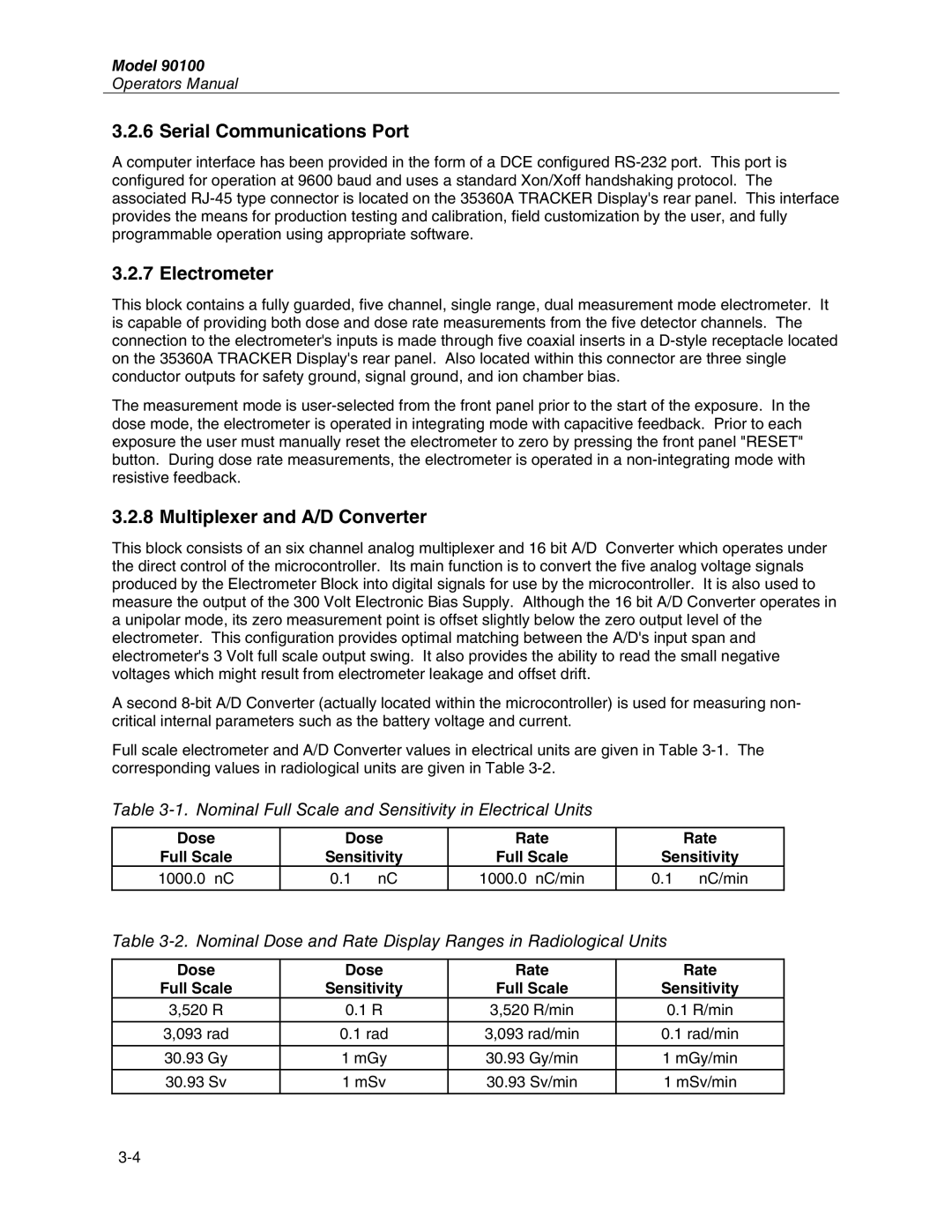
Full scale electrometer and A/D Converter values in electrical units are given in Table
Table
Dose | Dose | Rate | Rate |
Full Scale | Sensitivity | Full Scale | Sensitivity |
1000.0 nC | 0.1 nC | 1000.0 nC/min | 0.1 nC/min |
|
|
|
|
Table 3-2. Nominal Dose and Rate Display Ranges in Radiological Units
Dose | Dose | Rate | Rate |
Full Scale | Sensitivity | Full Scale | Sensitivity |
3,520 R | 0.1 R | 3,520 R/min | 0.1 R/min |
|
|
|
|
3,093 rad | 0.1 rad | 3,093 rad/min | 0.1 rad/min |
|
|
|
|
30.93 Gy | 1 mGy | 30.93 Gy/min | 1 mGy/min |
|
|
|
|
30.93 Sv | 1 mSv | 30.93 Sv/min | 1 mSv/min |
|
|
|
|