GC, GBC, GSMS specifications
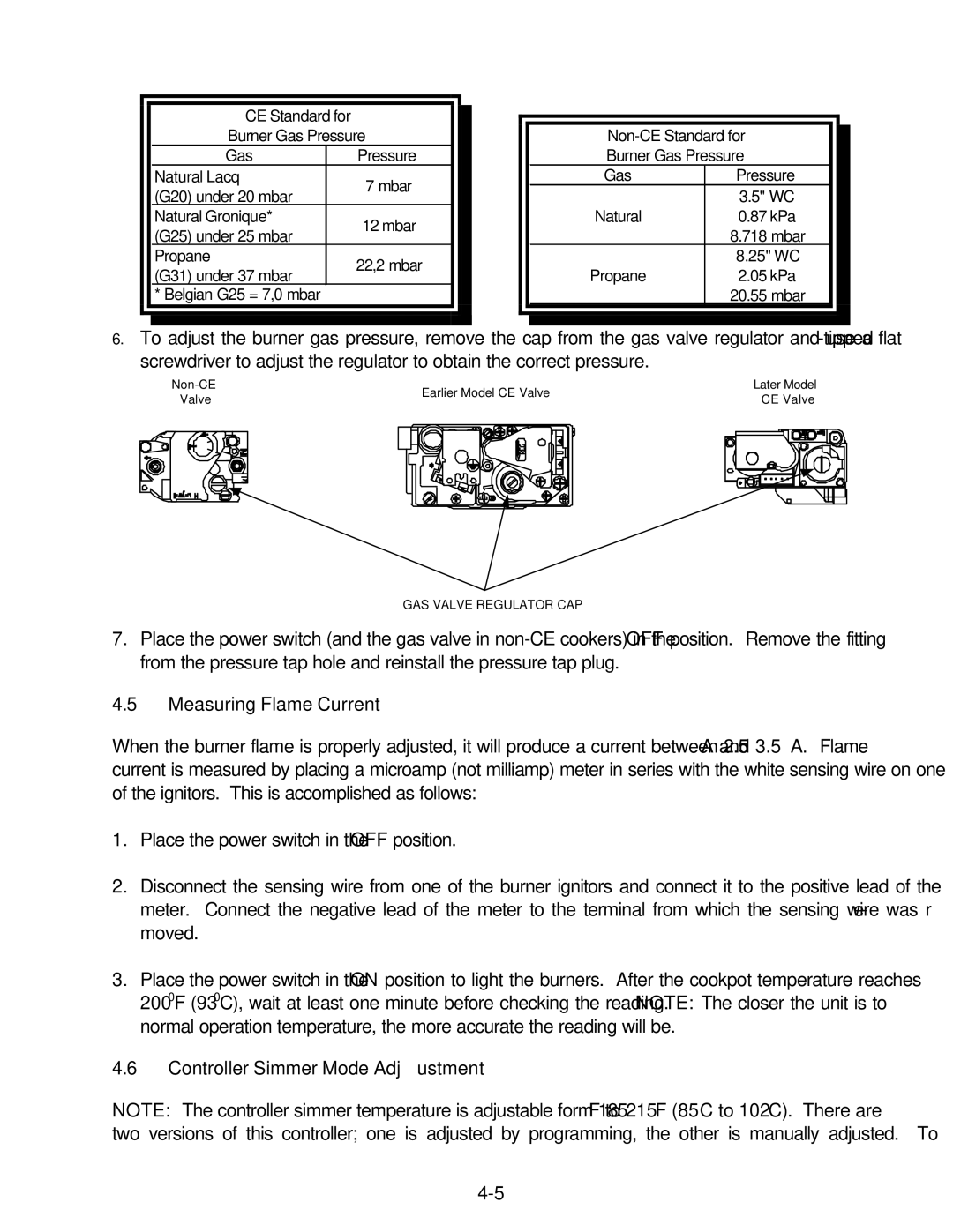
The Frymaster GSMS, GBC, and GC series are advanced fryers designed to meet the demands of busy commercial kitchens. Renowned for their efficiency, reliability, and technology, these fryers are integral to restaurants, snack bars, and food service operations looking to elevate their frying capabilities.One of the standout features of the Frymaster GSMS series is its ability to deliver consistent results with minimal effort. Equipped with smart technology, these fryers automatically adjust cooking times and temperatures to ensure food is cooked perfectly every time. This not only enhances food quality but also reduces the chances of operational errors, making it ideal for operators of all skill levels.
The GBC series is designed for versatility, featuring multiple fry pots. This allows different foods to be cooked simultaneously without the risk of cross-contamination. Whether you’re frying chicken, French fries, or doughnuts, the GBC series accommodates a wide variety of menus, helping restaurants maximize their offerings. Additionally, the models are energy efficient, significantly lowering operational costs associated with energy consumption.
The GC series represents the pinnacle of frying technology, integrating innovations that streamline cooking processes. One such innovation is the built-in filtration system that cleans oil during operation, extending its life and ensuring high-quality frying. This system not only enhances food flavor but also minimizes the need for frequent oil changes, significantly reducing waste and operational costs.
Another key characteristic across these Frymaster lines is their user-friendly control panels. These intuitive controls allow quick access to cooking settings and oil management, making the user experience seamless. Operators can easily monitor and adjust frying operations, which helps maintain peak performance and efficiency across a busy kitchen.
Moreover, safety features are paramount in these fryer models. Enhanced safety measures including automatic shut-off systems, temperature limit controls, and built-in alarms provide operators peace of mind in a fast-paced environment.
In summary, the Frymaster GSMS, GBC, and GC series fryers exemplify modern frying technology with their automation, versatility, and energy efficiency. These fryers not only support high-volume cooking but also prioritize safety and consistency, making them essential tools for any food service operation aiming for excellence.

