Fujitsu MPB3054AT, MPB3032AT manual Read circuit, 5 Frequency characteristic of programmable filter

Models: MPB3043AT MPB3021AT MPB3052AT MPB3032AT MPB3054AT

1 180
Download 180 pages 25.81 Kb
Page 55
Image 55
4.6.3Read circuit

4.6.3Read circuit

The head read signal from the PreAMP is regulated by the automatic gain control (AGC) circuit. Then the output is converted into the sampled read data pulse by the programmable filter circuit and the adaptive equalizer circuit. This clock signal is converted into the NRZ data by the 8/9 GCR decoder circuit based on the read data maximum-likelihood-detected by the Viterbi detection circuit, then is sent to the HDC.

(1)AGC circuit

The AGC circuit automatically regulates the output amplitude to a constant value even when the input amplitude level fluctuates. The AGC amplifier output is maintained at a constant level even when the head output fluctuates due to the head characteristics or outer/inner head positions.

(2)Programmable filter

The programmable filter circuit has frequency noise component and waveform of the read signal.

a low-pass filter function that eliminates unnecessary high a high frequency boost-up function that equalizes the

Cut-off frequency of the low-pass filter and boost-up gain are controlled from each DAC circuit in read channel by an instruction of the serial data signal from MPU (M1). The MPU optimizes the cut-off frequency and boost-up gain according to the transfer frequency of each zone.

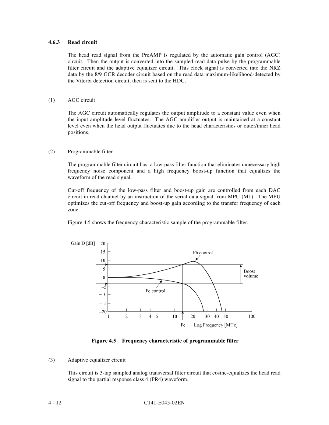
Figure 4.5 shows the frequency characteristic sample of the programmable filter.

Figure 4.5 Frequency characteristic of programmable filter

(3)Adaptive equalizer circuit

This circuit is 3-tap sampled analog transversal filter circuit that cosine-equalizes the head read signal to the partial response class 4 (PR4) waveform.

4 - 12

C141-E045-02EN

Page 55
Image 55
Fujitsu MPB3054AT, MPB3032AT, MPB3052AT, MPB3021AT, MPB3043AT Read circuit, 5 Frequency characteristic of programmable filter