1. INSTALLATION
Note: Dimensions for the cutout are different depending on the mounting location, indoor or out- door. For the outdoor mouting, ask dockyard to construct a waterproof case for the display unit.
2.Make four pilot holes for
3.Insert the sponge to the display unit from the rear side.
4.Set the display unit to the cutout and fasten the display unit with four
5.Set a cosmetic cap to each fixing hole on the front panel. See page
Desktop or table underside mount
The display unit can be mounted on a desktop or on the underside of a table using the optional hanger. See the outline drawing for details.
Hanger assembly (Type: OP26-8, Code No.: 000-016-313-00)
Name | Type | Code No. | Qty |
|
|
|
|
5x20 | 4 | ||
|
|
|
|
Binding head screw | M5x12 | 4 | |
|
|
|
|
Hanger assy. | 1 | ||
|
|
|
|
1.Remove the hanger mounting plate from the hanger assembly.
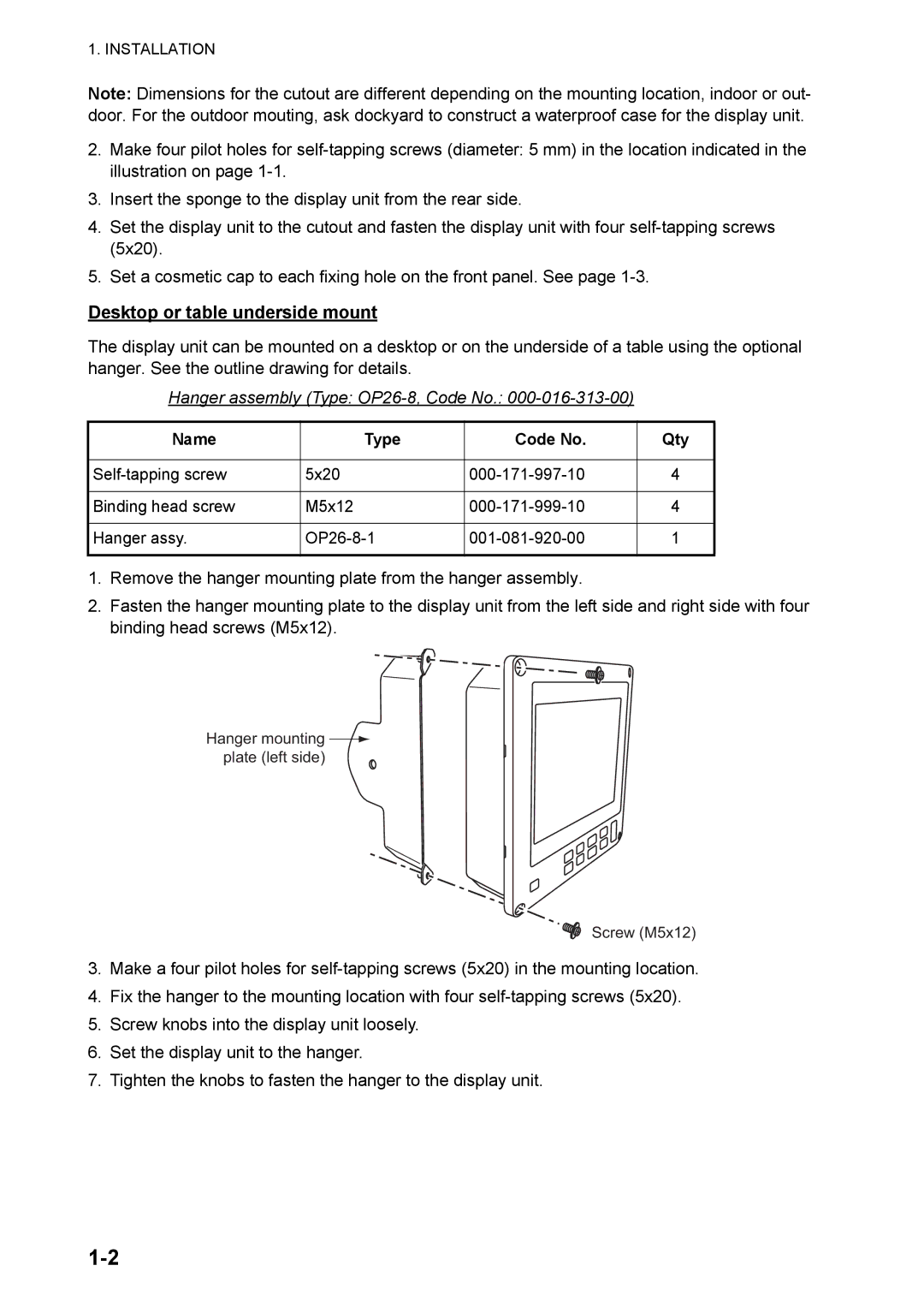
2.Fasten the hanger mounting plate to the display unit from the left side and right side with four binding head screws (M5x12).
Hanger mounting ![]() plate (left side)
plate (left side)
Screw (M5x12)
3.Make a four pilot holes for
4.Fix the hanger to the mounting location with four
5.Screw knobs into the display unit loosely.
6.Set the display unit to the hanger.
7.Tighten the knobs to fasten the hanger to the display unit.