2. WIRING
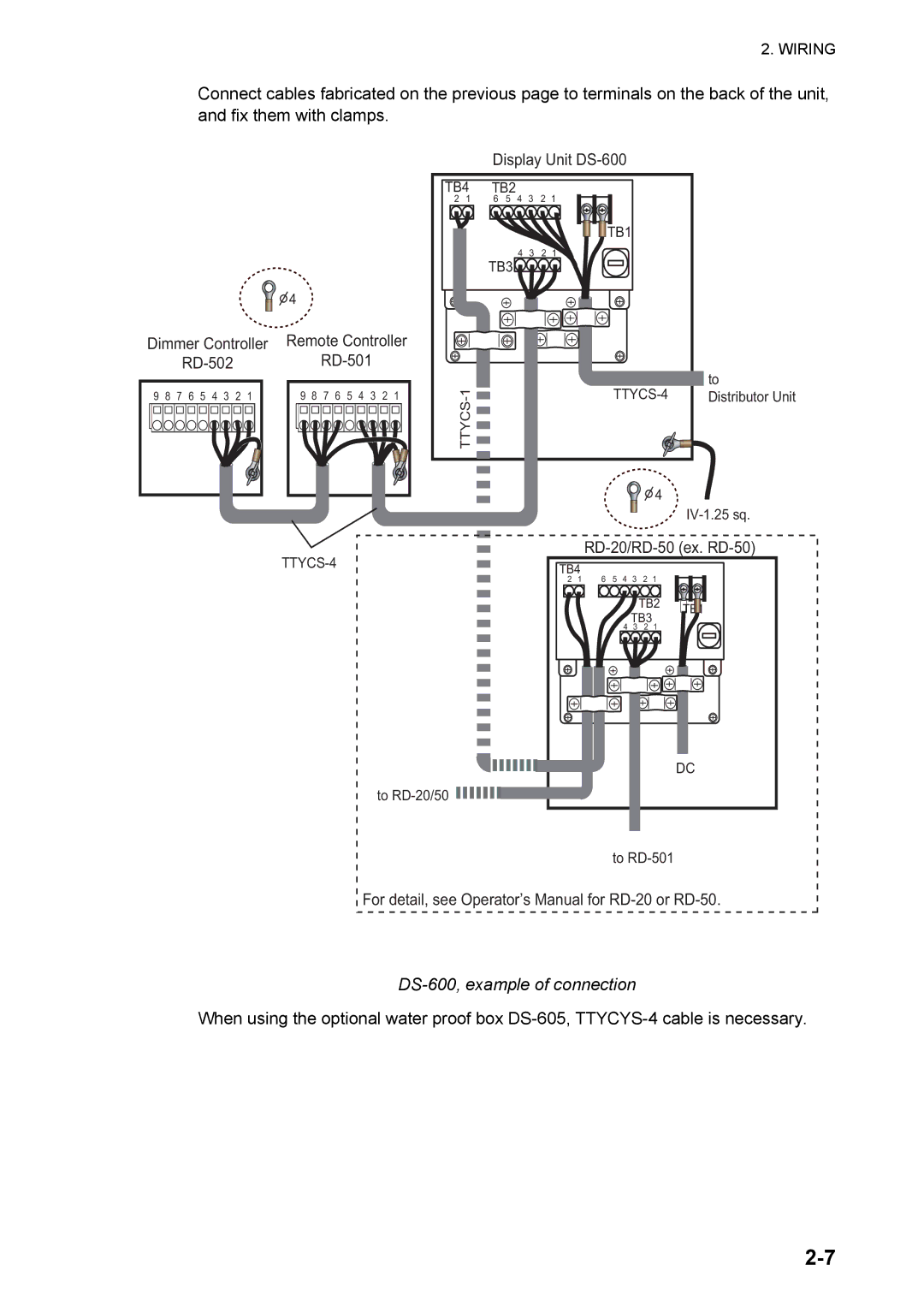
Connect cables fabricated on the previous page to terminals on the back of the unit, and fix them with clamps.
![]()
![]() 4
4
Display Unit
TB4 | TB2 | 4 | 3 | 2 | 1 | ||
2 | 1 | 6 | 5 | ||||
|
|
|
|
|
|
| TB1 |
|
| TB3 | 4 | 3 | 2 | 1 | |
|
|
|
|
|
| ||
Dimmer Controller
9 | 8 | 7 | 6 | 5 | 4 | 3 | 2 | 1 |
Remote Controller
9 | 8 | 7 | 6 | 5 | 4 | 3 | 2 | 1 |
to | ||
Distributor Unit | ||
TTYCS |
|
|
| 4 |
|
RD-20/RD-50 (ex. RD-50)
TB4
2 1 6 5 4 3 2 1
TB2 ![]() TB1
TB1
TB3
4 3 2 1
to ![]()
DC
to
For detail, see Operator’s Manual for
DS-600, example of connection
When using the optional water proof box