Security
N4131
Introduction
Content
Installation
Web-Based Management
Switch Operation Power Over Ethernet Overview
What is PoE?
Troubleshooting
Chapter
Package Contents
Product Description
Remote and Centralize Management installation
Powerful Security
Power over Ethernet of GE-DS-82-PoE
How to Use this Manual
Product Features
Physical Port
Priority queues on all switch ports Traffic classification
Layer 2 Features
Quality of Service
GE-DS-82-PoE
Multicast
Security
Management
Product Specifications
Power over Ethernet GE-DS-82-PoE Only
Dram
LED
Vlan
Power over Ethernet PoE Standard
Quality of Service
Access Control List
PoE Power Supply Type
Max. number of Class Standards Conformance Safety
Power Pin Assignment
PoE Power Budget
Standards Compliance
Switch Front Panel
Hardware Description
10/100Mbps TP Interface GE-DS-82, GE-DS-82-PoE
Gigabit TP Interface
Reset button
LED Indications
Gigabit SFP Slots
System
Per 10/100Base-T RJ-45 port
Per 10/100/1000Base-T port/SFP interfaces
Switch Rear Panel
Per 10/100Base-TX, PoE interfaces Port-1 to Port-8
Power Notice
Console Port
Switch Installation
Desktop/Shelf Installation
Rack-mount Installation
Secure the brackets tightly, but do not over tighten screws
SFP Transceiver Installation
Mounting the GE-DS-82 in a rack
Approved GE Security SFP Transceivers
1000Base-SX/LX SFP transceiver
Connect the fiber cable
Remove the transceiver module
Pulling out the SFP transceiver
Installation
Requirements
Summary
This chapter covers the following topics
Management Access Overview
Web Browser Management
Management Methods Comparison
Web Browser Setup
Login to the managed Switch
PC / Workstation With IE Browser RJ-45/UTP-Cable IP Address
Login screen
PC / Workstation With Snmp application
Administration Console
SNMP-Based Network Management
IP Address
Direct Access
PC connected to Switch with RS-232 serial cable
Telnet Setup
Protocols
Virtual Terminal Protocols
Log on to the Console
New Connection dialog window
Snmp Protocol
Management Architecture
Web-Based Management
About Web-based Management
Requirements
Logging on to the Switch
Http//192.168.0.100
Main Web
Panel Display
Main Menu
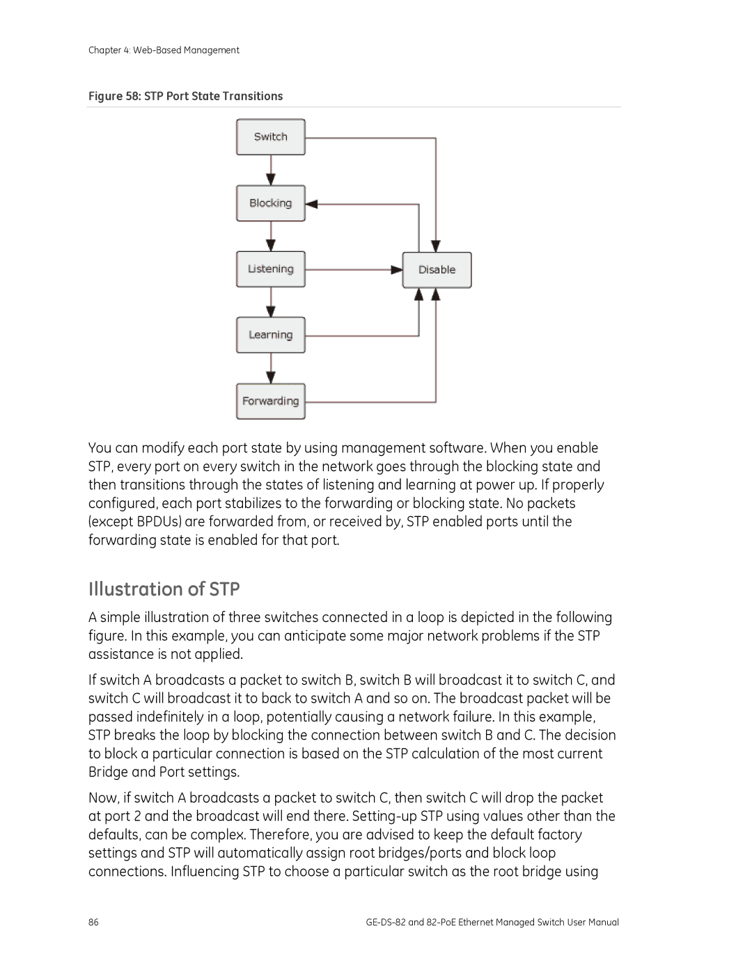
Port states are illustrated as follows
System
System Information
Misc Config
Basic
This page includes the following fields
Object Description
Broadcast Storm Filter
Mode
IP Configuration
What is an IP address?
How do I get one for this box?
IP Configuration
Objectdescription
Subnet Mask
Snmp Configuration
Snmp Overview
Gateway
Snmp Community
System Options
System Contact
System Name
System Location
Snmp Status
Community strings serve as passwords. See the table below
Community Strings
Trap Managers
Community Enter the community string for the trap station
SNMPv3 Groups
Enter the IP address of the trap manager
Group Name
View Name
SNMPv3 View
Security Name
Included Excluded
View Mask Hexadecimal
SNMPv3 Access
View Subtree
Digits
SNMPv3 usm-user
Firmware Upgrade
Tftp Firmware Upgrade
This page include the following fields
Click System then Web Firmware Upgrade
Http Firmware Upgrade
To open the Firmware Upgrade screen, do the following
Firmware Upgrade screen is displayed as in Figure
Configuration Backup
Tftp Restore Configuration
Tftp Backup Configuration
Configuration Backup interface
Factory Default
System Reboot
Reboot the switch. Click reboot to reboot the system
This page includes the following settings
Syslog Setting
Port Configuration
Port Control
Port Control interface
BSF
Port Status
Port Statistics
Tx Bad Packet
Port Port number Link Status of linking-Up or Down State
Or receive any packet
Via this port
Port Sniffer
Port Mirror application
Sniffer Type
Monitored Port
Protected Port
Protected
Vlan Configuration
Vlan Overview
Web-Based Management
802.1Q Tag
Static Vlan Configuration
Port-Based Vlan
Static Vlan interface
Create a Vlan and add member ports to it
Port-based Vlan interface
Port
Vlan Name
Group ID
Member
Tagged
Understand nomenclature of the Switch
802.1Q Vlan
Untagged
Vlan Group Configuration
Vlan Group Configuration
Vlan Group Configuration interface
Vlan ID
UnTag Member
Vlan Filter
Pvid
Ieee 802.1Q Tunneling Q-in-Q
Ingress Filtering
In-Q Port Setting
QinQ Vlan \ QinQ Port Setting screen in appears
In-Q Tunnel Setting
Object
In-Q Tunnel Setting interface
Gvrp Setting
To configure Gvrp
Enable global Gvrp function
Object Description Gvrp
Gvrp Table
Object Description Vlan ID
Rapid Spanning Tree
Theory
Bridge Protocol Data Units
Creating a Stable STP Topology
STP Port States
Illustration of STP
STP Port State Transitions
This example, only the default STP values are used
Before Applying the STA Rules
STP Operation Levels
Default Value
STP Parameters
Parameter Description
128
Rstp System Configuration
Parameter Description Default Value
Port Priority
Protocol Version
Rstp mode
Forward Delay Time
RSTP, 802.1w
Root Bridge Information
Rstp Bridge Status page screenshot
Rstp Port Configuration interface
Costs on the least cost path to the Root Bridge
Admin Non STP
Admin P2P
Admin Edge
Path Cost
Trunking
Recommended STP Path Cost Range
Aggregator Setting
Lacp
Aggregator Information
System Priority
Work ports
Assigning 2 ports to a trunk group with Lacp disabled
Lacp enabled
Switch 1 configuration
Trunk group
Switch 2 configuration
Switch 2 configuration interface
Switch 1 Aggregator Information
State Activity
Forwarding and Filtering
Dynamic MAC Table
MAC Table Entries
You can add static MAC address in the switch MAC table here
Static MAC Table
Add the Static MAC Address
MAC Filtering
Vlan ID for the entry
MAC Filtering interface
MAC Address Enter the MAC address that you want to filter
Igmp Snooping
About the Internet Group Management Protocol Igmp Snooping
Multicast flooding
Igmp Versions 1
Octets Type Response Time
Igmp Querier
Igmp State Transitions
Igmp Configuration
Will be displayed in Igmp status section
QoS Configuration
Understand QOS
QoS Configuration
Priority Queue Service settings
802.1Q Tag and 802.1p priority
All High before Low
First Come First Service
Weighted Round Robin
802.1p priority
QoS PerPort Configuration
TOS/DSCP
TOS MBZ
TOS/DSCP Configuration
Precedence
DiffServ
TOS/DSCP Port Configuration
Object Description TOS/DSCP
Dscp
Access Control List
QoS Configuration TOS/DSCP Port Status
Action
Object Description Default Value
IPv4 ACL
Packet Type
TCP
Ether Type
Non-IPv4 ACL
Packet Type/Binding box should select Non-IPv4
Type
Binding
Port Id
MAC Limit
MAC Limit Configuration
MAC Limit
Limit
MAC Limit Port Status
This table displays current MAC Limit status of each port
802.1X Configuration
Understanding Ieee 802.1X Port-Based Authentication
802.1x device role
125
EAP message exchange
System Configuration
System information \ Misc Configuration\ 802.1x Protocol
On the Radius Server
802.1x Port Configuration
Shared Key
NAS, Identifier Set the identifier for the Radius client
802.1x Per Port Setting interface
Misc Configuration
Power Over Ethernet
Power over Ethernet Powered Device
Power Management
PoE Configuration
Power Allocation
PoE Temperature Unit
Power limit mode
PoE PSU Status
Power Limit
PD Classifications
To configure Dhcp Relay
Dhcp Relay and Option
Lldp
Use this page to change Lldp parameters
Lldp Configuration
PerPort Configuration
Value is
Lldp Per Port Configuration
Lldp Status
Login in to the Console Interface
Console Management
GE-DS-82-PoEConsole Login screen
Configure IP address
Show the current IP address
Configure IP address
Subnet Mask Gateway
Commands Level
Following table lists the CLI commands and description
Exec
144
Switch# configure
Switch config #
Operation Notice
Command Help
System Commands
Command Line Editing
Key Function
Syntax
Switch Static Configuration
Port Configuration and show status
Parameters
Port priority disable low high port-list
Enable or disable port flow control
Port flow enable disable enable disable port-list
Set port effective ingress or egress rate
Port jumboframe enable disable port-list
Port-id specifies the port to be shown
Show protected port information
Trunk Configuration
Trunking Commands
Show trunking information
Lacp Commands
Syntax Lacp system-priority Parameters
Syntax Show lacp port port-idParameters
Virtual LANs
Show Lacp information by port
Port-idspecifies the port to be shown
Vlan Mode Port-based
Display the current Vlan mode
Disabled port-based dot1q specifies the Vlan mode
Advanced 802.1Q Vlan Configuration
Change Vlan mode
Ingress filters configuration
Add or edit Vlan entry
Syntax Vlan add 1-4094 Name cpu-portno-cpu-port List List
Delete Vlan entry
Show Vlan entry information
Specifies the Vlan id, null means all valid entries. e.g
Vlan
Show port default Vlan id
Show static Vlan entry information
Syntax Show vlan pvid List Parameters
162
Show Vlan filter setting
Set ingress filter rules
Syntax Show vlan filter List Parameters
Forward
Misc Configuration
No mac-age-time Description
Mac-age-time Parameters
Collision-Retry setting
Syntax Collision-Retry off 16 32 Parameters
Syntax Hostname name-str Parameters
Administration Configuration
Change Username / Password
No hostname
Syntax Ip default-gateway ip-addr
User can configure the IP setting and fill in the new value
Set the default gateway IP address
Show IP address, subnet mask, and the default gateway
Set switch as dhcp client, it can get ip from dhcp server
Reboot switch
Reset to Default
Show dhcp enable/disable
Copy tftp running config flash Description
Tftp Update Firmware
Restore Configure File
Download firmware from Tftp server
Backup Configure File
Copy running config flash tftp Description
Ip-addr specifies the IP address of the Tftp server
No mac-limit Description
Mac-limit Description
Syntax Mac-limit port-list
Port Mirroring Configuration
Syntax Mirror-port rx tx both port-idport-list Parameters
Show port monitoring information
Quality of Service
Set 802.1p priority
Syntax Port priority disable 0-7 port-list Parameters
Per Port Priority
No mac-address-table static mac-addr Description
MAC Address Configuration
Mac-address-table static Description
Syntax No mac-address-table static mac-addrvlan-id
Smac-address-table static Description
Show mac-address-table static Description
Show mac-address-table multicast Description
Show smac-address-table multicast Description
Syntax Spanning-tree forward-delay 4-30 Parameters
STP/RSTP Commands
Spanning-tree forward-delay Description
Spanning-tree hello-time Description
Spanning-tree priority Description
Spanning-tree maximum-age Description
Syntax Spanning-tree maximum-age 6-40 Parameters
Syntax Spanning-tree priority 0-61440 Parameters
Show spanning-tree port Description
Syntax Show spanning-tree port port-list Parameters
Spanning-tree debug Description
No spanning-tree port mcheck Description
Spanning-tree protocol version Description
Syntax Spanning-tree protocol-version stp rstp Parameters
Syntax No spanning-tree port mcheck port-list Parameters
No spanning-tree port non-stp Description
Syntax No spanning-tree port non-stp port-list Parameters
Spanning-tree point-to-point mac Description
Show snmp status Description
System Options
Snmp /no snmp Description
Snmp system-name Description
Snmp system-contact Description
Snmp system-location Description
Syntax Snmp system-location location-str Parameters
Syntax Snmp system-contact contact-str Parameters
Delete Snmp community string
Community Strings
Set Snmp community string
Syntax No snmp community community-str Parameters
Remove trap receiver IP address and port number
Trap Managers
Syntax Snmp trap ip-addr community-str 1..65535 Parameters
Syntax No snmp trap ip-addr 1..65535 Parameters
Syntax No igmp fastleave
Syntax No igmp querier
Syntax No igmp CrossVLAN
Show Igmp snooping information
Enable/disable Igmp snooping debugging output
Syntax No igmp debug
Syntax Show igmp status router groups table Parameters
Radius-server host Description
802.1x Protocol
Dot1x Description
Radius-server key Description
Syntax Dot1x timeout tx-period 0..65535 Parameters
Syntax Dot1x timeout quiet-period 0..65535 Parameters
Dot1x timeout tx-period Description
Radius-server nas Description
Dot1x timeout radius-server Description
Dot1x timeout supplicant Description
Syntax Dot1x timeout supplicant 1..300 Parameters
Syntax Dot1x timeout radius-server 1..300 Parameters
Set 802.1x per port information
Syntax Dot1x port fu fa au no port-list Parameters
Show 802.1x per port information
Ipv4 ACL commands
Syntax No acl 1-220 Parameters
Show ACL group information
Acl addedit 1-220 permitdeny 0-4094 ipv4 0-255 Description
Add or edit ACL group for Ipv4
Non-Ipv4 ACL commands
Commands
Acl addedit 1-220 qosvoip 0-4094 Description
Add or edit ACL group for non-Ipv4
SIP/SMAC binding commands
Binding
Show Binding group information
Add Binding group
Syntax Bind add 1-220 Abcdef 0-4094 A.B.C.D 1-26 Parameters
Command Level
Power over Ethernet Commands GE DS-82-PoE
Show System Power over Ethernet information
Global Configuration Example
Global Configuration
Show per PoE port information
Syntax Show poe status port-list Parameters
Poe temperature-protection enablex4 Description
Configure PoE Over Temperature Protection
Configure PoE System
Configure System PoE power limit mode information
No Limit
Configure PoE -- Port
Enabling or disabling the port POE injects function
Syntax Poe priority Critical High Low port-list Parameters
Poe maximum-power Description
208
Address Table
Learning
Forwarding & Filtering
Store-and-Forward
Auto-Negotiation
Power Over Ethernet Overview
What is PoE?
How Power is Transferred Through the Cable
PoE System Architecture
When to install PoE?
Consider the following scenarios
References
Stages of powering up a PoE link
Microsemi /PowerDsine Linear Tech
PoE Provision Process
Start-up
Line Detection
Classification
Operation
DC Disconnect
Power Overloads
Power Disconnection Scenarios
AC Disconnect
Link LED is not lit Solution
Performance is poor Solution
Why the Switch doesnt connect to the network? Solution
Switch does not power up Solution
While IP Address be changed or forgotten admin password
Switchs RJ-45 Pin Assignments
1000Mbps, 1000Base T
10/100Mbps, 10/100Base-TX
Standard cable, RJ-45 pin assignment
Tx + transmit Rx + receive Tx transmit Rx receive Not used
Side
Straight Cable
Side SIDE2
Crossover Cable