Air-Cooled Product
Electrical formulas
Automatic Operating Sequences
Problem 12 No Battery Charge
147
Specifications
Engine
Fuel Consumption
Mounting Dimensions
Right Side View
Major Features
Door removed
Part General Information
Generator Identification Part
Introduction
Neutral Floating
Rainproof Enclosure Fitted Rated Ambient Temp 40C
Installation basics
Transfer Switch / Load Center
Selecting a Location
Grounding The Generator
Installation basics Part
Typical Installation
Power Source And Load Lines System Control Interconnections
Natural Gas Fuel Interconnections
Control Wires from Transfer Switch
Non-Prepackaged Interconnections Part
Non-Prepackaged Interconnections
PRE 08 HSB AIR-COOLED Generators Single & V-TWIN Engines
Reconfiguring The Fuel System
Preparation Before Use Part
General
Fuel Requirements
Install the battery, door and close the roof
Preparation before use
Engine Oil Recommendations
Meters
Vom
Measuring AC Voltage
Measuring DC Voltage
Testing, cleaning and drying Part
Measuring Current
Measuring Resistance
Electrical Units
Ohm’s Law
Volts Amps Ohms
Visual Inspection
Insulation Resistance
Megohmmeter
ONE 1 Second
Repeat between Wire 2 and Stator Lead
Stator Insulation Resistance Test 12-20 kW
Stator Insulation Resistance Test 10 kW
Cleaning The Generator
Rotor Insulation Resistance Test 10 kW
Rotor Insulation Resistance Test 12-20 kW
Drying The Generator
Low Battery
High Temperature Switch
Low Oil Pressure Shutdown
Overspeed Shutdown
Engine-generator protective devices Part
Overcrank Shutdown
Operating Instructions
Control Panel
KW Installation Assistant
Operating instructions Part
To Select Automatic Operation
Manual Transfer To Standby Manual Startup
Automatic operating parameters
Seconds then re-crank if additional crank cycles exist
Automatic operating parameters Part
Manual
Auto
Exercise
Part AC Generators
Rotor Assembly
Engine-Generator Drive System
AC Generator
Stator Assembly
Description & components
Description & components Part
Brush Holder And Brushes 12-20 kW
Other AC Generator Components
Main Line Circuit Breaker
Rotor Residual Magnetism
Field Boost 12-20 KW
Operational analysis Part
Operation 8/10 kW
Operation 12-20 kW
Startup
Troubleshooting flowcharts
Troubleshooting flowcharts Part
Troubleshooting flowcharts
Problem 3 Generator Produces Low Voltage at No-Load
Problem 4 Generator Produces High Voltage at No-Load
Units with
Safety
Test 1 Check Main Circuit Breaker
Test 2 Check AC Output Voltage
Results
Diagnostic tests Part
Remove jumper lead connected to Wire 4 and Wire 15B
Procedure
Test 4 Fixed Excitation Test Rotor Amp Draw Test
Test 5 Wire Continuity 12-20 kW
Diagnostic tests
Example
Test 7 Testing The Stator With a Vom 12-20 kW
Reconnect Wire
Test 6 Check Field Boost 12-20 kW
Repeat using stator lead Wire
Test Control Panel Wires for Continuity
Test 8 Test Brushless Stator
Repeat using stator lead
Repeat using Wire
Test 9 Check Capacitor
Meter lead to Wire
Repeat using Wires 2
Test 10 Test DPE Winding on Brushless units
Measured
Remove Wire 4 from the voltage regulator
Test 11 Resistance Check Rotor Circuit 12-20 kW
Test 12 Check Brushes And Slip Rings 12-20 kW
If Continuity was measured in Steps 5 and 6 proceed to Step
Test 13 Test Rotor Assembly 12-20 kW
Test 14 Check AC Output Frequency
Remove air cleaner cover to access stepper motor
Test 16 Check Stepper Motor Control V-twin Engine Units
Loosen the governor clamp bolt Figure
Test 17 Check And Adjust Voltage Regulator 12-20 kW
Pull ARM this Direction to Close Throttle
Refer back to flow chart
Test 18 Check Voltage Frequency Under Load
Test 20 Check Engine Condition
Test 21 Field Flash Alternator KW Units
Construction of Energizing Cord
Page
Transfer
General Enclosure
Item Description
Transfer Mechanism
Transfer Relay
Neutral Lug
Manual Transfer Handle
Terminal Block
Utility N1 and N2
Fuse Holder
Fuses F1, F2
Fuses F3
Is a schematic for a typical W/V-Type transfer switch
Operational Analysis
Is a wiring diagram for a typical W/V-Type transfer switch
Operational analysis
Utility Source Voltage Available
SW1
Generator Power Available, Waiting to Transfer
Utility Source Voltage Failure
Transfer To Standby
Transfer Action to Standby Position
Generator Powering Load
Utility Restored
Utility Restored, Generator Still Providing Output to Load
Utility Restored, Transfer Switch De-energized
Utility Restored, Transfer Relay De-energized
Utility Restored, Retransfer Back To Utility
Utility Restored, Retransfer Back to Utility
Transfer Switch In Utility
Transfer Switch in Utility
Troubleshooting flow charts Part
Introduction To Troubleshooting
Problem 7 In Automatic Mode, No Transfer to Standby
Troubleshooting flow charts
Problem 9 Blown F1 or F2 Fuse
Check N1 & N2
Problem 11 No Battery Charge Pre-Wire Load Center
Problem 12 No Battery Charge Rtsn & Rtse Transfer Switch
Problem 13 No Battery Charge GenReady Load Center
Problem 14 No Battery Charge Load Shed Transfer Switch
Test 26 Check Voltage at Terminal Lugs E1, E2
If the generator has been shut down, proceed as follows
Test 27 Check Manual Transfer Switch Operation
Manual Transfer Switch Operation
Test 28 Check 23 and 15B Wiring
Reconnect the J2 connector to the PCB
PROCEDURE/ Results
Remove the J2 connector from the circuit board
Test 29 Test Transfer Relay Tr
Set VOM to measure DC voltage
Test 31 Check Wire
Test 30 Standby Control Circuit
SW1
Output
Test 32 Utility Control Circuit
N2A
Test 33 Test Limit Switch SW2 and SW3
Test 34 Check Fuses F1 and F2
Test 35 Check N1 and N2 Wiring
Test 36 Check N1 and N2 Voltage
Replace blown fuses as needed
Test 37 Check Utility Sensing Voltage at the Circuit Board
Test 38 Check Utility Sense Voltage
Test 39 Check Voltage at Terminal Lugs N1, N2
Transfer Switch
Generator
Test 40 Check Battery Charger
Test 42 Check Wire 0 and Wire15B Pre-wire load center
Measure across points a and C VAC should be measured
Measure across points M and N VDC should be measured
Rtsn & Rtse Transfer Switch
Test 45 Check Wire 0/15B Rtsn & Rtse Transfer Switch
Measure across points E and F VAC should be measured
15B
Test 43, 44, and 45 Rtse Transfer Switch Test Points
Test 48 Check Wire 0/15B GenReady Load Center
Disconnect the J2 connector from the printed circuit board
Section
Load Shed Transfer Switch
Measure across points C and D VAC should be measured
Measure across points E and D VAC should be measured
LSS
ATS
LSC
Test 51 Check Wire 0 and Wire 15B Load Shed Transfer Switch
Part DC Control
Auto-Off-Manual Switch
Description and components Part
Terminal Strip / Interconnection
Circuit Board
Description and components
Amp Fuse
KW Printed Circuit Boards and J1 Connector
J2 Connector PCB END J1 Connector Stepper Motor
Harness END Remote Wireless Connection
Harness END Remote Wireless Connection N1/N2 Connector
PCB END Harness END
17 and 20 kW Printed Circuit Board and J1 Connector
Choke Solenoid Connector Pin Number Identification
Menu System Navigation
Description
Components
Stator
Circuit Condition Utility Source Voltage Available
Initial Dropout of Utility Source Voltage
Circuit Condition Initial Dropout of Utility Source Voltage
Utility Voltage Dropout and Engine Cranking
Circuit Condition Engine Cranking
Engine Startup and Running
Circuit Condition Engine Startup and Running
Initial Transfer to the Standby Source
Circuit Condition Initial Transfer to Standby
Utility Voltage Restored / Re-transfer to Utility
Circuit Condition Utility Voltage Restored
Engine Shutdown
Circuit Condition Retransfer to Utility and Engine Shutdown
Controller Switch BAD Replace Controller Assembly
Problem 17 Engine Cranks but Won’t Start
Readjust Replace Choke Solenoid BAD
Problem 19 Shutdown Alarm/Fault Occured
Problem 20 7.5 Amp Fuse F1 Blown
Problem 21 Generator Will Not Exercise
Problem 22 No Low Speed Exercise
Test 56 Check Position Of Auto-Off Manual Switch
Test 58 Auto-Off-Manual Switch Twin Only
Test 57 Try a Manual Start
Test 61 Check Battery
Test 59 Test Auto Operations
Test 60 Check 7.5 Amp Fuse
Test Battery Condition
Typical Battery Load Tester
Test 62 Check Wire 56 Voltage
If battery voltage is indicated in refer back to flow chart
Test 63 Test Starter Contactor Relay V-twin Only
Set a VOM to measure DC voltage
Reconnect Wire 13 to the SCR
Test 64 Test Starter Contactor Single Cylinder Engine
Test 65 Test Starter Motor
Shorted, open or grounded armature
Checking the Pinion
Pinion
Pinion
Tools for Starter Performance Test
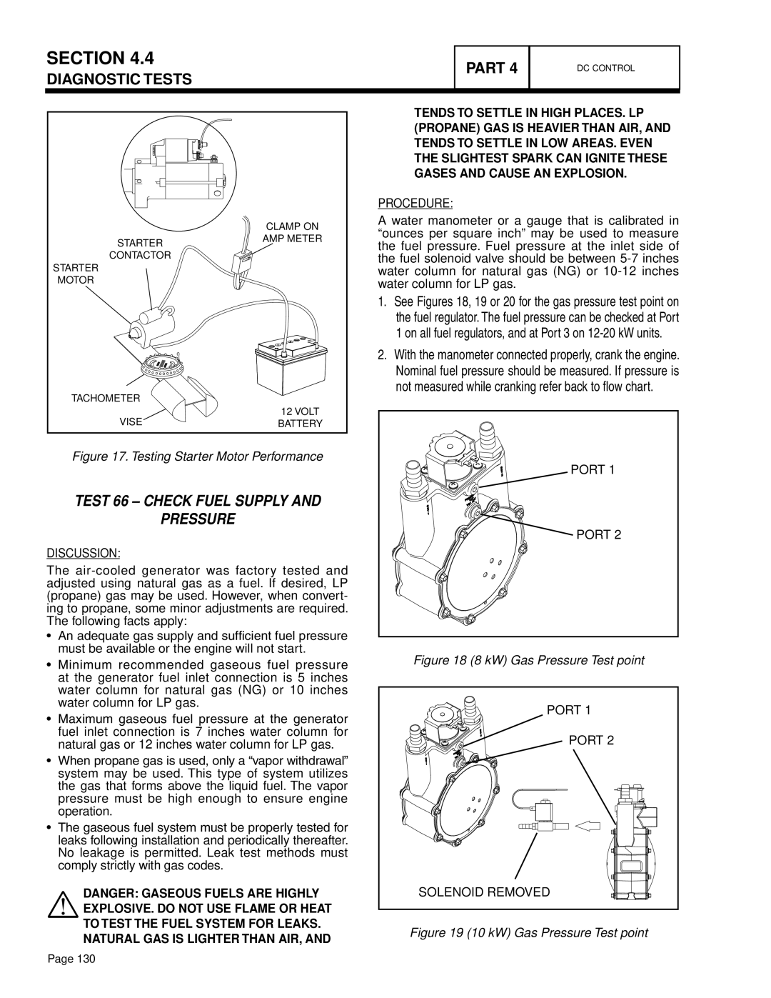
Test 66 Check Fuel Supply Pressure
Port
Solenoid Removed
Test 67 Check Circuit Board Wire Output
12-20 kW Gas Pressure Test point
Disconnect the C3 Connector
Test 68 Check Fuel Solenoid
Test 69 Check Choke Solenoid
Approximately 3.7 ohms should be measured
Solenoid De-Energized, Choke Closed KW Units
Disconnect the C3 Connector Set a VOM to measure DC voltage
Disconnect C3 Connector Set a VOM to measure resistance
Test 70 Check for Ignition Spark
KW Choke Solenoid
Test 71 Check Spark Plugs
Test 73 Check Shutdown Wire
Remove a spark plug
Repeat Steps 1 through 8 on remaining cylinder
Check Compression
Test 74 Check and Adjust Ignition Magnetos
Depending on engine type, do the following
Setting Ignition Magneto Armature Air Gap
Magneto
Cylinder One Back, Short
Test 75 Check Oil Pressure Switch Wire
Navigate to the Digital inputs display screen
Check engine crankcase oil level
With oil level correct, try starting the engine
Test 76 Check High Oil Temperature Switch
Test 77 Check and Adjust Valves
Replace switch if it fails the test
Remove the High Oil Temperature Switch
Test 78 Check Wire 18 Continuity
Set the AUTO-OFF-MANUAL switch to the Manual position
Ball Stud JAM NUT
Test 79 Test Exercise Function
Test 80 Check Cranking and Running Circuits
Record the current date and time of the unit
Choke Solenoid
8kW
Test 81 Check to see if Low Speed Function is enabled
Disconnect Wire 4 and Wire 0 from the Voltage Regulator VR
Test 82 Check operation Choke Solenoid
If the solenoid closed, replace the controller
Part Operational Tests
Manual Transfer Switch Operation
System functional tests Part
Electrical Checks
Set the generator main line circuit breaker to OFF or open
System functional tests
Generator Tests Under Load
Setting The Exercise Timer
Verify that the AUTO-OFF-MANUAL switch is set to Auto
Checking Automatic Operation
Part Disassembly
Major Disassembly Part
Front Engine Access
Remove control harnesses
Major Disassembly
Section
Section
Major Disassembly
Section
Section
Section
Section
Engine mount nuts with ground wires. See Figure
Torque Requirements Unless Otherwise Specified
Part Electrical Data
Wiring Diagram, 8 kW Home Standby Part
Drawing #0G7945
Wiring Diagram, 8 kW Home Standby
Schematic, 8 kW Home Standby Part
Drawing #0G8511
Part Schematic, 8 kW Home Standby
Wiring Diagram, 10 kW Home Standby Part
Drawing #0G7946
Part Wiring Diagram, 10 kW Home Standby
Schematic, 10 kW Home Standby Part
Drawing #0G8512
Part Schematic, 10 kW Home Standby
Wiring Diagram, 14 kW Home Standby Part
Drawing #0G7947
Part Wiring Diagram, 14 kW Home Standby
Schematic, 14 kW Home Standby Part
Drawing #0G8513
Part Schematic, 14 kW Home Standby
Wiring Diagram, 17 kW Home Standby Part
Drawing #0G7948
Part Wiring Diagram, 17 kW Home Standby
Schematic, 17 kW Home Standby Part
Drawing #0G8514
Part Schematic, 17 kW Home Standby
Wiring Diagram, 20 kW Home Standby Part
Drawing #0G8186
Part Wiring Diagram, 20 kW Home Standby
Schematic, 20 kW Home Standby Part
Drawing #0G8515
Part Schematic, 20 kW Home Standby
Transfer Switch, 9/10/12/16 circuit
Wiring Diagram, Home Standby
Part Wiring Diagram, Home Standby
Schematic, Home Standby
Drawing #0G7959
Page
Page
Page
MyGenerac.com