Owner’s Manual
Models RED40 RED40ST
NOTICE
•What to do if you smell gas
Homeowner Reference Information
A. Congratulations
3 Maintenance and Service
Table of Contents
Safety Alert Key
Installer Guide
13 Finishing
14 Appliance Setup
15 Troubleshooting
= Contains updated information
WARRANTY PERIOD
B. Limited Lifetime Warranty
LIMITED LIFETIME WARRANTY
WARRANTY COVERAGE
This warranty is void if
B. Limited Lifetime Warranty continued
WARRANTY CONDITIONS
WARRANTY EXCLUSIONS
B. Glass Specifications
D. High Altitude Installations
1 Listing and Code Approvals
A. Appliance Certification
Installation of Carbon Monoxide Detectors
C. Clear Space
A. Gas Fireplace Safety
2 Operating Instructions User Guide
B. Your Fireplace
erate fireplace with fixed glass assembly removed
E. Fixed Glass Assembly
D. Decorative Doors and Fronts
G. Before Lighting Fireplace
LIGHTING INSTRUCTIONS IPI
H. Lighting Instructions IPI
Final inspection by
FOR YOUR SAFETY READ BEFORE LIGHTING
•Some people may be sensitive to smoke and odors
J.Frequently Asked Questions
I. After Fireplace is Lit
Initial Break-inProcedure
Remote Control
3 Maintenance and Service
A. Maintenance Tasks-Homeowner
Glass Cleaning
Firebox
B.Maintenance Tasks-QualifiedService Technician
Gasket Seal and Glass Assembly Inspection
Venting
Figure 4.1 Typical System
Getting Started
A. Typical Appliance System
Installer Guide
D. Inspect Appliance and Components
B. Design and Installation Considerations
C.Tools and Supplies Needed
A. Selecting Appliance Location
5 Framing and Clearances
Figure 5.2 Appliance Locations RED40ST
1/2 IN
1/2 IN. C
C. Clearances
B. Constructing the Appliance Chase
MINIMUM FRAMING DIMENSIONS
Non-CombustibleMantels
D. Mantel and Wall Projections
Dimensions of Non-Combustibles
Combustible Mantels
H Min. Ft
6 Termination Locations
A. Vent Termination Minimum Clearances
Roof Pitch
V= VENT TERMINAL X = AIR SUPPLY INLET
= AREA WHERE TERMINAL IS NOT PERMITTED
Covered Alcove Applications
B. Vent Table Key
7 Vent Information and Diagrams
E. Vent Diagrams
A. Approved Pipe
H1 Maximum
Top Vent - Horizontal Termination
Venting with 1 elbow
V1 Minimum
H1 + H2 Maximum
1. Top Vent - Horizontal Termination - continued
Venting with 2 elbows
INSTALLED HORIZONTALLY
H2 V2 H1 V1
1. Top Vent - Horizontal Termination
Venting with 3 elbows
continued
Exhaust restrictor Instructions
Top Vent - Vertical Termination No Elbows
V = 3 ft Min. 1m, 50 ft. Max. 15.2 m
V2 H1 V1
Top Vent - Vertical Termination
H1 + H2 Maximum
DIRECT VENT WITH 5 in. / 8 in. DIAMETER DVP PIPE
Between ceiling firestops
8 Vent Clearances and Framing
A. Pipe Clearances to Combustibles
B. Wall Penetration Framing
C. Install the Ceiling Firestop
Vaulted Ceiling Installation
D. Install Attic Insulation Shield
Flat Ceiling Installation
A. Appliance Preparation
9 Appliance Preparation
•Sagging or loose insulation
B. Securing and Leveling the Appliance
Setting the Fireplace into the Framing
WARNING! Risk of Fire! Prevent contact with
C. Active Convection Technology
A. Assemble Vent Sections
10 Installing Vent Pipe DVP Pipe
Pilot hole
B. Assemble Slip Sections
C. Secure The Vent Sections
D. Disassemble Vent Sections
E. Install Decorative Ceiling Components
CAUTION! Risk of Cuts, Abrasions or Flying Debris
F. Install Metal Roof Flashing
G. Assemble and Install Storm Collar
CAULK
H. Install Vertical Termination Cap
Figure 10.20 Venting Through the Wall
J. Install Horizontal Termination Cap
B. Gas Pressure
11 Gas Information
A. Fuel Conversion
•Ensure adequate ventilation
C. Gas Connection
12 Electrical Information
A. Wiring Requirements
B. IntelliFire Ignition System Wiring
C. Optional Accessories Requirements
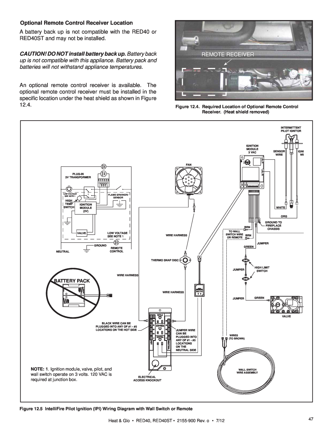
REMOTE RECEIVER
Optional Remote Control Receiver Location
COLOR PRODUCED
D. Optional LED Lighting Circuit
SWITCH TRIPPED
KNOCKOUT
E. Electrical Service and Repair
F. Junction Box Installation
G. Active Convection Blower Replacement
FAN MOUNT FASTENER
SIDE BURNER SCREW
Figure 12.18. Removed Mounting Plate
SLOT ON BLOWER HOUSING
BLOWER TAB ON MOUNTING PLATE
Figure 12.17. Remove Mounting Plate
Finishing Instructions
13 Finishing
A. Splatter Guard
B. Framing and Finishing Instructions
Figure 13.1 Finishing Details
Finish and Sealing Joints
Finishing Around Opening with Gypsum Wallboard
Painting
Dimensions of Combustibles
C. Mantel and Wall Projections
Figure 13.6 Framing and Framing Materials-RED40ST
D. Facing Material
Figure 13.5 Framing and Framing Materials-RED40
Figure 13.7 Overlap Fit Method
Non-CombustibleFinish Materials
0 - 1 inch thickness-OverlapFit Method
13-1/8IN
0 Inches to 4 Inches Thick Inside Fit Method
Figure 13.9 Inside Fit Method
42-3/4IN
Figure 13.11. Mesh Front Installation
E. Mesh Fronts
ASSEMBLY
MESH FRAME ASSEMBLY
D. Accessories
14 Appliance Setup
A. Remove Fixed Glass Assembly
C. Clean the Appliance
Removing Fixed Glass Assembly
H. Fixed Glass Assembly
I. Install the Mesh
J. Air Shutter Setting
Possible Cause
15 Troubleshooting
A. IntelliFire Ignition System
Symptom
IntelliFire Ignition System - continued
16 Reference Materials
A. Appliance Dimension Diagram
A F G
Figure 16.2 Appliance Dimensions RED40ST
M N O P
T R Q S
DVP-AS2
B. Vent Components Diagrams
Figure 16.2 DVP vent components
DVP-TRAPK1
B. Vent Components Diagrams continued
DVP-TRAP1
DVP-TRAP2
31 in
330 mm
8-1/8in
13 in
206 mm
PART NUMBER
Optional Wire Harness
DESCRIPTION
Stocked
C. Service Parts
RED40
at Depot
40 in Landscape See-ThruDV Fireplace
RED40ST
RED40,RED40ST
#13 Control Assembly
Service Parts List
#14 Valve Assembly
Service Parts
RED40, RED40ST
Stocked
15.2
#15 Base Pan No Lights with Media
15.3
15.1
15.4
15.2
15.1
15.3
16.1
#16 Base Pan With Lights and Media
Stocked at Depot
16.3
16.4
16.2
16.3
16.1
RED40-NNPNo lights, No Rock, Porcelain
#17 Base Pan No Lights or Media with
Porcelain or No refractory
RED40-NNNNo lights, No Rock, No Refractory
RED40ST-NNGNo lights, No Rock, Granite
Stocked at Depot
RED40ST-NNNNo lights, No Rock, No Refractory
RED40ST-NNPNo lights, No Rock, Porcelain
#22 Porcelain --With Media
#19 Granite --No Media
#20 Porcelain --No Media
#21 Granite --With Media
#21 Granite --With Media
NOTES
D. Contact Information