Revised for Addition of HL-1650/1670N/3260N/2460
Revised for Addition of HL-2400Ce/3400CN
Ver. B
Ver. C
Page
Table of Contents
HP-GL Graphics Language
Glossary
Control code
Control panel reset
Graphics mode initial settings
Font
LSB
RAM
ROM
Tiff
Page
Chapter Introduction
About the Manual
About the Manual
Graphics
Using Word Processing Packages and Spreadsheets
Areas of USE
Programming
Font Development
Introduction
Chapter PCL
Contents
Using Fonts
Using Graphics
Macros
Index
Command List
Environments Job Control
Using graphics
Status Readback
Introduction
Controlling the Printer
Control Codes
Esc&s0C 27381154867 1Bh26h73h30h43h
Escape Sequences
Esc&k#G 2738107#71 1Bh26h6Bh#47h
Esc&s1C 27381154967 1Bh26h73h31h43h
EscZ 2790 1B5A
Display functions mode
EscY 2789 1B59
Environments
Factory default environment
User default environment
Modified print environment
Esc&l#A 2738108#65 1Bh26h6Ch#41h
JOB Control
Size
Postcard
Output tray
Esc&l#G 2738108#71 1Bh26h6Ch#47h
Paper source
Esc&l#H 2738108#72 1Bh26h6Ch#48h
Left long-edge offset registration
Esc&l#U 2738108#85 1Bh26h6Ch#55h
Esc&a#G 273897#71 1Bh26h61h#47h
Esc&l#Z 2738108#90 1Bh26h6Ch#5Ah
Esc&l#S 2738108#83 1Bh26h6Ch#53h
EscCRFD
Esc&l1T 27381084984 1Bh26h6Ch31h54h
EscE 2769
EscCR!#R
EscCRAI 27136573 1Bh0Dh41h49h
EscCRGL
EscCRAB 27136566 1Bh0Dh41h42h
EscCRI 271373 1Bh0Dh49h
Logical
Physical
Printable area
Text area
Portrait page dimensions
4200 2550 4080 150
Landscape page dimensions
3300 2550 3180 150
3150 2175 3030 3507 2480 3389 2952 2078 2834
Esc&a#M 273897#77
Esc&u#D 2738117#68 1Bh26h75h#44h
Esc&a#L 273897#76
Esc9 2739 1Bh39h
Resetting the horizontal margins
Setting the top margin
Esc&l#E 2738108#69 1Bh26h6Ch#45h
Esc&l#C 2738108#67 1Bh26h6Ch#43h
Setting the vertical motion index VMI
Setting the horizontal motion index HMI
Sample file
Text length
Setting line spacing
Esc&l#D 2738108#68 1Bh26h6Ch#44h
Esc&l#F 2738108#70 1Bh26h6Ch#46h
Perforation skip
Length
Esc&l#P 2738108#80 1Bh26h6Ch#50h
Esc&l#L 2738108#76 1Bh26h6Ch#4Ch
Esc&a#V 273897#86
Esc&a#R 273897#82
Esc*p#Y 2742112#89 1Bh2Ah70h#79h
Horizontal cursor positioning units
Horizontal position Horizontal cursor positioning columns
Esc&a#C 273897#67
Esc*p#X 2742112#88 1Bh2Ah70h#58h
Horizontal cursor positioning decipoints
Positioning the cursor using control codes
Using the cursor position stack
Esc&a#H 273897#72
Esc&a#P 273897#80
Esc= 2761 1Bh3Dh
Esc&l#O 2738108#79 1Bh26h6Ch#4Fh
Lprint Brother
Using Fonts
Introduction
Brother Original Fonts
Microsoft Windows 3.1 TrueType Compatible Fonts
BR-Script Fonts
Bound fonts
Esc3@
Criteria for font selection
Symbol set
Symbol collections
Type of character spacing
Stroke weight
Typeface
Escf#Wdata 2749102#87
Font Selection Commands
Esc*c#R 274299#82
Bit Value Designated Use
Character Requirements for MSL Symbol index
Character Requirements for Unicode Symbol index
Selecting the symbol set
Symbol map Array of UI
Symbol set control command
Escsymbol set ID 2740
Escs#C 2740115#67 1Bh28h73h#43h
Escsymbol set ID 2741
Symbol Set Set primary font Symbol set
Escs#C 2741115#67 1Bh29h73h#43h
Escs#H 2740115#72 1Bh28h73h#48h
Escs#P 2740115#80 1Bh28h73h#50h
Escs#P 2741115#80 1Bh29h73h#50h
Escs#H 2741115#72 1Bh29h73h#48h
EscCR!#H 271333#72 1Bh0Dh21h#48h
Escs#V 2740115#86 1Bh28h73h#56h
Escs#V 2741115#86 1Bh29h73h#56h
EscCR!#V 271333#86 1Bh0Dh21h#56h
Escs#T 2740115#84 1Bh28h73h#54h
Escs#B 2740115#66 1Bh28h73h#42h
Escs#B 2741115#66 1Bh29h73h#42h
Escs#T 2741115#84 1Bh29h73h#54h
OCR-A
Typeface Set primary Set secondary HL-1050/1250
Font
OCR-B
Esc&d#D 2738100#68
Transparent print data
Esc&p#X character codes 2738112#88 1Bh26h70h#58h
Esc&d@
Esc*c#F 27384299#70
Downloadable font manipulation
Esc&*c#D 27384299#68
Esc#X 2740#88 1Bh28h#58h
Sending the font descriptor
Creating Downloadable Fonts
Downloading
Escs#W font descriptor data 2740115#58 1Bh28h73h#88h
Bitmap font
Special Bitmap font
Intellifont Scalable Bound font
Intellifont Scalable Unbound font
Byte 15 MSB LSB
Value Width
Value Posture
Upright Italic Alternate Italic Reserved
Value Structure
600 dpi
Symbol set name Symbol set ID Symbol set name
OCR a OCR B OCR M
Value Stroke Weight
Value Width type
Value Vendor
MSL Symbol Index
Bit Field Designated Use
Unicode Symbol Index
MSL Symbol Index Character Complement bits
Unicode symbol index character complement bits
If font is compatible with 7-bit Ascii otherwise set to
Sending a character code
Sending a character descriptor and data
Byte Data
Bitmap continuation data Byte 0-1 Data
Intellifont scalable font data
Compound character data of Intellifont scalable font
Intellifont-scalable contour data
Continuation data for Intellifont scalable contour data
TrueType scalable font
TrueType character descriptor Byte Data
PCL
Landscape character
For example
Using Graphics
Source, Pattern and Destination
Set source transparency
Set pattern transparency
Esc*v#O 2742118#79
Set area fill identity
Esc*c#G 274299#71
For 300 dpi
User-defined pattern command
Esc*c#W data 274299#87
Set pattern reference point
Set pattern type
User-defined pattern control
Esc*c#Q 274299#81
Esc*v#T 2742118#84
Pattern example
REM --- Background
Plotting Rectangles
Next Gray REM --- Draw a Pattern Using 8 Gray Scales
EscCRRL 1Bh0Dh52h4Ch
Raster Graphics
EscCRRO 1Bh0Dh52h4Fh
EscCRRM 1Bh0Dh52h4Dh
Esc*b#Y 274298#89
Esc*r#T 2742114#84 1Bh2Ah72h#54h
Esc*r#S 2742114#83 1Bh2Ah72h#53h
Esc*b#M 274298#77
# = 5 indicates that adaptive compression is to be used
Tiff
Optional offset count byte =
File Length
Ccitt G3 & G4
APT
OFF
Esc*b#Cimage data 274298#67 1Bh2Ah62h#43h
Esc*r#A 2742114#65 1Bh2Ah72h#41h
Esc*b#Wdata 274298#87 1Bh2Ah62h#57h
Esc*rB 274211466 1Bh2Ah72h42h
Raster graphics example
REM --- Transfer Raster Graphics
Horizontal 1200-dpi image format mode Raster Graphic Mode
ESC*b##W Block 1 Block 2 Block
Number of repeats
Esc%#B 2737#66 1Bh25h#42h
Enter HP-GL/2 mode
Vector Graphics
Picture Frame
Macros
Purpose of a Macro
Esc&f0X 27381024888 1Bh26h66h30h58h
Defining a Macro
Esc&f#Y 2738102#89 1Bh26h66h#59h
Esc&f1X 27381024988 1Bh26h66h31h58h
Esc&f3X 27381025188 1Bh26h66h33h58h
Running a Macro
Esc&f2X 27381025088 1Bh26h66h32h58h
Esc&f4X 27381025288 1Bh26h66h34h58h
Handling Macros
EscCR!#E 271333#69
AppleTalk configuration
Execute data
Laser diode video interface port of the MIO port is opened
MIO video I/O port control
Laser diode video interface port of the MIO port is closed
Entity Status
Status Readback
Memory Status request
Status Response
ESC*s#T 2742115#84 1Bh2Ah73h#54h
Status Response Syntax
Set status readback location type
Set status readback location unit
Entity status response
Inquire status readback entity
ESC*s#I 2742115#73 1Bh2Ah73h#49h
Font response
Download fonts
Bound scalable fonts
Unbound scalable fonts
Location type 1 currently selected font
Font extended response
Permanent download fonts
Macro response
Symbol set response
Symbol set response may be shown as follows
Use-defined pattern response
ESC*s1M 27421154877 1Bh2Ah73h31h4Dh
Entity error codes
Free space command
ESC&r#F 2738114#70 1Bh26h72h#46h
ESC*s#X 2742115#88 1Bh2Ah73h#58h
Index
Raster transfer
Dimensions
Pitch
Secondary font
Type of character spacing
Status response Memory 101
Transfer start
VMI
Chapter PCL5C
Color Palettes
Introduction
Color Modes
Using Simple Color Mode Set Simple Color
Command
ESC*r#U 2742114#85 1Bh2Ah72h#55h
Short Format
Using PCL Color Mode Set PCL Color Setting
ESC*v#W 2742118#87 1Bh2Ah76h#57h
ESC*b1V 11001100B
ESC*r1A
ESC*b1V 10101010B
ESC*b1V 11110000B
Ffh 80h 40h
ESC*b#V r, r, r, r, r... → Plane
ESC*b#V g, g, g, g, g... → Plane
00h 00h 00h
White reference for value #1, #2, #3
Bits/value #1, #2, #3
Long Format
Using HP-GL/2 Color Mode
Black reference for value #1, #2, #3
Color Palettes
Push/Pop Palette
ESC*p#P 2742112#80 1Bh2Ah70h#50h
Set Destination Raster Width
Color Graphics
Start Raster Transfer
Set Destination Raster Height
Send Raster Data by Plane
Enter HP-GL/2 Mode
Set Scale Algorithm
Set Render Algorithm
Set Monochrome Mode
Enhance Output
ESC*t#J 2742116#74 1Bh2Ah70h#4Ah
Download Dither Matrix
User-defined Pattern Command
Set Gamma Correction
Function Equivalent Condition Instruction
Initialize Set Instruction Command
PC Pen Color Command
Color White Black Red Green Yellow Blue Magenta Cyan
NP n
NP Number of Pens Command
CR Color Range Command
Index
Chapter HP-GL/2
Command Syntax
Character Plot Instructions
Command List
10/10/03
Introduction
Terminology
Absolute and Relative Plotting
Fills
Parameters
Command Syntax
Mnemonic
Separators
Scaling Points P1 and P2
HP-GL Graphics Window
Units
Scaling
Preparing to Print Graphic Images
DF Default set instruction
Commands
Initialize Commands
Function Equivalent Condition
HP-GL/2 origin
Returns the graphics mode to initial conditions
Initialize set instruction
IP P1X, P1Y ,P2X, P2Y
Plot Area and Unit Setting Instructions
IP Input scaling point
IR Input relative scaling points
Min Y coordinate of P1
SC Scale
Min X coordinate of P1
Type type of scaling
Lprint INSP1
Sample
RO Rotate coordinate system
IW Window
IW X1, Y1, X2, Y2
RO q
PU X,Y
Pen Control and Plot Instructions
PU Pen up
PD Pen down
PR Relative coordinate pen move
PA Plot absolute
PA X, Y
PR X, Y
Qc Arc angle in degrees
AA Draw absolute arc
Arc centre X coordinate
AT Absolute arc three point
AR Draw relative arc
AR X, Y, qc, qd
AT X 1, Y 1, X 2, Y 2 , qd
RT Relative arc three point
PE Polyline encoded
CI r, qd
This
CI Circle plot
BZ Bezier absolute
BR Bezier relative
BR X1, Y1, X2, Y2, X3, Y3 . . . X1, Y1, X2, Y2, X3, Y3
BZ X1, Y1, X2, Y2, X3, Y3 . . . X1, Y1, X2, Y2, X3, Y3
PM ms
PM Polygon mode
Polygon group
EA Edge rectangle absolute
EP Edge polygon
ER Edge rectangle relative
ER X, Y
EW Edge wedge
RA Fill rectangle absolute
RA X, Y
WG Fill wedge
RR Fill rectangle relative
RR X, Y
FP Fill polygon
Specifies Non-zero winding fill method
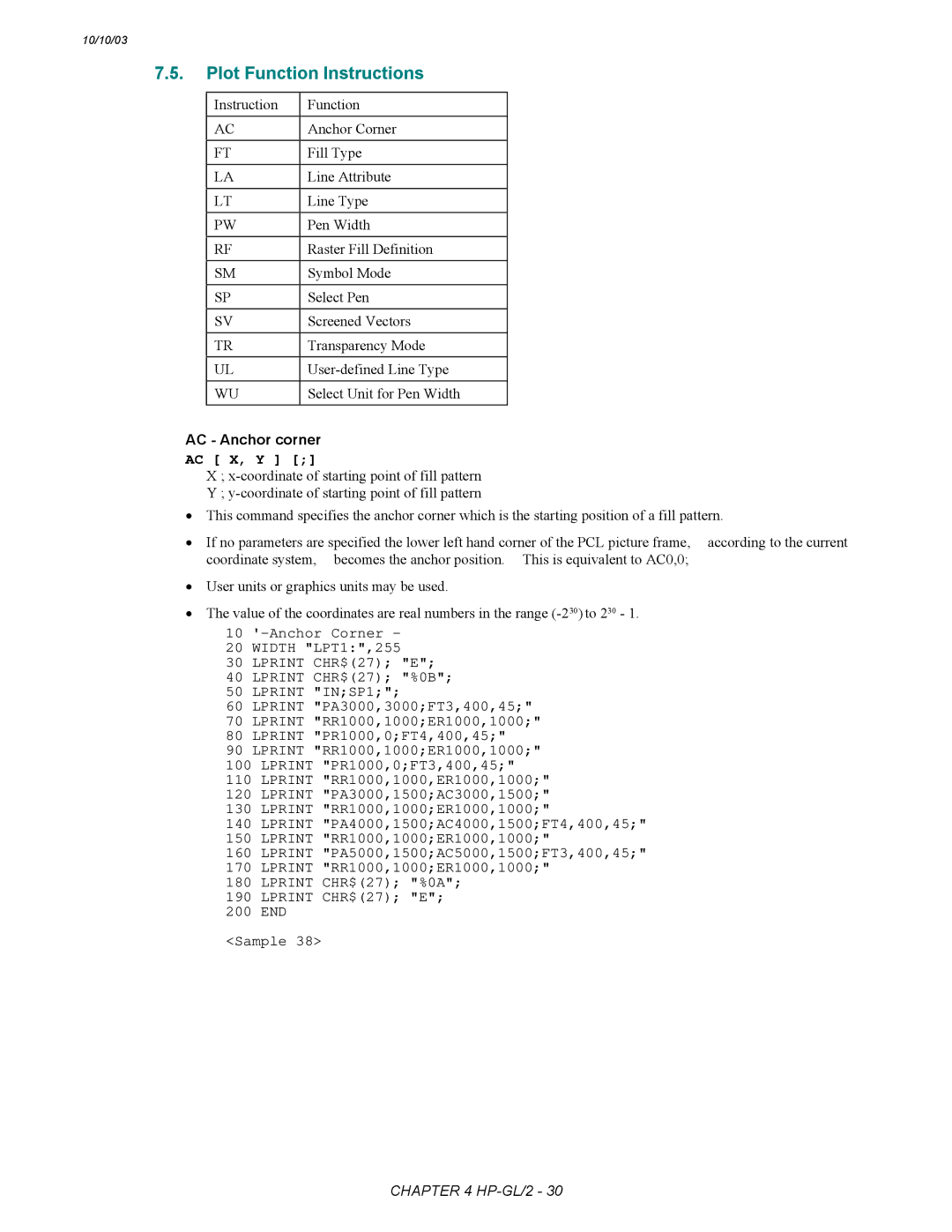
AC X, Y
Plot Function Instructions
AC Anchor corner
Fill type Option
FT Fill type
FT n, d, q
LA Line attribute
LA l, v , l , v , l
Any line residue are saved
LT Line type selection
LT , n , p ,m n Line pattern number
RF Raster fill definition
PW Pen width
PW w, ,p w width
RF i , w, h, p
SV s , option1, option2 s screen type
SM c
SP n n pen number
TR Transparency mode
TR n
WU Select unit for pen width
UL User-defined line type
UL i ,g
Character Plot Instructions
Introduction
SD Define standard font
Valu Name
Number
9999
Alternate italic Attribute = 6 Stroke weight Meaning
Attribute = 2 Spacing Value
SA Select alternate font
AD Define alternate font
SS Select standard font
FN Select secondary font
FI Select primary font
FI font-ID
LB Character plot
LO Label origin
DT Define label terminator
DT c , m c Character
LO p
DI Absolute direction
DI run, rise
DR Relative direction
DR run, rise
CP Relative character movement
DV Define variable text path
DV path ,line
CP spaces ,lines
SI Set absolute character size
CF Character fill mode
CF fill , pen
SI width, height
SL Character slant
SR Set relative character size
SR width, height
SL tan φ
ES width ,height
TD mode
SB n
Transparent Data Width LPT Lprint CHR$27 E Lprint CHR$27 %0B
Relative coordinate pen move Relative direction
Absolute arc three point
Window
10/10/03
Chapter PJL
HOW to USE PJL
Device Attendance Commands
About PJL
Postscript jobs
Case of Using PJL with a Non-PJL Printer
PCL jobs
Other printer languages
@PJL Enter Language = emulation Crlf
Format 3 @PJL command words CR LF
PJL Syntax and Format
Format 1 ESC%-12345X
Invalid Commands
Variables
PJL Job Requirement
HOW to USE PJL
Overview
PJL Code PCL Job Postscript Job
Command Group
Command Group Command Description
Execute Command
Kernel Commands
UEL Command
ESC%-12345X
@PJL Comment remarks Crlf
Enter Command
Comment Command
Explicit switching
Printer Language Switching
There are three methods of switching printer languages
Implicit switching
Name = job name
JOB Separation Commands
JOB Command
EOJ Command
@PJL EOJ Name = job name Crlf
Environment Commands
Print environment
PJL reset conditions
Remember these points about environments
PJL environment variables
Initialize
General PJL Environment Variables
Contextswitch
OFF Timeoutsleep
Resolution
Autosleep
Powersavetime Mediatype RET Imageadapt
Password
Powersave
Bidi
DL, MONARCH, Ledger
INTRAY1SIZE
LETTER, LEGAL, Executive
JISB4, LTRS, A4S
AUTO, MPTRAY, TRAY1
INTRAY5SIZE
Sourcetray
AUTO, TRAY1, TRAY2
LETTER, LTRS, Executive
JISB5, A4LONG, Postcard
TRAY2SIZE A3, JISB4, LEDGER, A4, A4S
EXECUTIVES, COM10, C5, DL
Oemfont
Defpaper A4, LETTER, Default
Errorprint OFF, ON, Exceptcdcc
Compabitmap
Ffsuppress
Faxringdelay
Traypriority MPT1T2T3T4, MPT4T3T2T1 T1T2T3T4 MP, T4T3T2T1MP
Lcddensity
PCL-Specific Variables
MONARCH, C5, DL, JISB5
Paper
LETTER, A4, Legal
LTRS, EXECUTIVES, B5S
EPSON-Specific Variables
IBM-Specific Variables
Or Permanent Soft Fonts
LTRS, Executives B5S
C1, C2, S HL-3260N
PostScript-Specific Variables
HPGL-Specific Variables
Scandinavian
ANSIASCII, CHRSET9825
Frenchgerman
SPANISHLATIN, Jisascii
AUTO, PCL , POSTSCRIPT, IBM
LETTER, LEGAL, A4, Exective
ON, OFF
EPSON, Hpgl
ENGLISH, FRENCH, German
Firstprint
NORMAL, MIDDLE, High
DUTCH, SPANISH, Italian
ISO85, WIN30, HPGERM, Hpspan Mctext
PostScript-Specific Variable
@PJL Default Lparm personality variable = value Crlf
Default Command
Initialize Command
Examples
Reset Command
Set Command
@PJL SET Lparm personality variable = value Crlf
ESC%-12345X@PJL Crlf @PJL Reset Crlf ESC%-12345X
Basic format of status readback responses
Status Readback Commands
Synchronization with the printer
Response Syntax
Inquire Command
@PJL Inquire Lparm personality variable Crlf
@PJL Inquire Lparm personality variable Crlf value Crlf
@PJL Dinquire Lparm personality variable Crlf
Dinquire Command
Example This example requests the PCL-specific settings
@PJL Dinquire Lparm personality variable Crlf value Crlf
Echo Command
@PJL Echo words Crlf
Ascii 33 to 255, SP, HT
Info Command
Parameter Valid characters
@PJL Info category Crlf
Information requesting
ID category
Font Cartridge Slots
Config category
Parameter Range of Characters Description
LCD
Memory category
Printer may send back the answer for the above Info command
Printer sends back the answer for the above command
Variables category
Printer may send back the answer for the above command
Status category
ORIENTATION=PORTRAIT 2 Enumeratedcrlf Portraitcrlf
Ustatus category
Verbose
Ustatus Command
Device
Timed
Status code
@PJL Ustatus variable = value Crlf
Device variable
JOB variables
Example When the following wrong PJL command is sent
Application sends the following commands to the printer
Variable
Timed variable
There are no parameters for this command
Ustatusoff Command
JOB Recovery
@PJL Rdymsg Display = message Crlf
Device Attendance Commands
Rdymsg Command
Display = message
@PJL Opmsg Display = message Crlf
Opmsg Command
Stmsg Command
@PJL Stmsg Display = message Crlf
If the operator press the Online key
ONLINE, Reset
Key
Demopage
PCL-specific variables 26, 31
Chapter Epson FX-850
Command List Introduction Emulation Details
NUL
DC4
Introduction
Emulation Details
Ignored Commands
Resolution
Syntax
Conventions
Control Panel
Escape sequence
Basic printer operations
Esc$n1n2 2736n1n2
EscSPn 2732n 1Bh20hn
Escan 2797n
Esc\n1n2 2792n1n2
Esc# 2735
Esc= 2761
Esc 2762
Escxn 27120n 1Bh78hn
EscEMn 2725n 1Bh19hn
EscCRmode 2713mode
EscCR!#R 271333#82 1Bh0Dh21h#52h
Esc9 2757
Set up
Line Spacing
EscDn1n2n3...NUL 2768n1n2n3...00 1Bh44hn1n2n3...00h
Using Tabs
Escjn 27106n 1Bh6Ahn
HT 09 09h
Esc/ n 2747n
Using Standard Characters
Escbnm1m2m3...NUL 2798nm1m2m3...00 1Bh62hnm1m2m3...00h
VT 11 0Bh
SI 15 0Fh
EscM 2777
Escpn 27112n 1Bh70hn
EscSI 2715
SO 27 0Eh
EscH 2772
EscWn 2787n
EscSO 2714
EscT 2784
Esc5 2753
EscSn 2783n
Escwn 27119n 1Bh77hn
Esc7 2755
Esc!n 2733n
Esc6 2754
EscIn 2773n
Esctn 27116n 1Bh74hn
Using customized characters
EscRn 2782n
Copy ROM character to RAM
Select standard / downloaded characters
Esc% nNUL 2737n00
Esc000
Esc*mn1n2image data 2742mn1n2
Select image mode
Reassign image mode
Esc? cm 2763cm
Print 9 bit image
Escan1n2 2792an1n2
Print double-density image
Print single-density image
EscKn 1n 2image data 2775n1n2
EscLn 1n 2image data 2776n1n2
EscZn 1n 2image data 2790n1n2
Print double-speed double-density image
Print quadruple-density image
Double-speed double-density image
Epson
Chapter IBM Proprinter
Notation Used in this Emulation Description
ESC
EscZn1n2image data Set quadruple-density image mode
Introduction
Character Set selection
Controlling the Printer
Notation Used in this Emulation Description
Data Conventions
BEL 07 07h
Basic Printer Operation
NUL 0 0h
ESC 27 1Bh
EscQ22 27815050
Automatic line feed
Esc5n 2753n
EscQ3 278151 1Bh51h32h
EscEMn 2725n 1Bh19hn
EscCNULn 27670n
Format
EscCn 2767n
EscXmn 2788mn
Esc1 2748
Set vertical tabs
Restore default tab settings
Set horizontal tabs
EscR 2782
Esc 2758
Using Characters
Esc6 2756
EscP n 2780n
SO 14 0Eh
Can 24 18h
Esc@n1n2n3n4n5n6 279164n1n2n3n4n5n6 1Bh5Bh40hn1n2n3n4n5n6
Esc-n 27126n 1Bh7Ehn
Escn 2795n 1Bh5Fhn
Select character font
Select a character from the All Character Code table
Escchar-code 2794Char-code 1Bh5EhChar-code
Sample
EscKn 1n 2image data 2775n1n2image data
Data
EscLn 1n 2image data 2776n1n2image data
Set double-speed, double-density image mode
EscYn 1n 2image data 2789n1n2image data
Set quadruple-density image mode
EscZn 1n 2image data 2790n1n2image data
Overline mode Length
Cancel
Feeder mode
Perforation skip Pitch Print quality
IBM Proprinter
Chapter BAR Code Control
Example Program Listings
Introduction
Print BAR Codes or Expanded Characters
ESC i n ... n \ 27105n ... n
Bar Code Style = s0 or S0
Bar Code Mode
Definition of Parameters
Quiet Zone
Bar Code Scaling Width only
Bar Code Human Readable Line On or Off
Expanded Character Rotation
Bar Code & Expanded Character Offset in the Y-axis
Expanded Character, Line Block Drawing & Box Drawing Width
Isbn UPC-E
Total 8 digits = 0 + 6 digits + 1 check digit
Bar Code Data Start
Check digit
Expanded Character Data Start
Box Drawing
Line Block Drawing
Codabar
Example Program Listings
Inter Leaved
Label Print
Chapter HP-GL
Command List Introduction
Command List
Coordinate System and Printing Area
HP-GL Syntax
Font Selection
Coordinate system
Printing area
3400CN/3260N/3450CN Letter Legal
Initialization and Default Setting Instructions
SC Xmin, Xmax, Ymin, Ymax
Xmin X coordinate of P1
PG Page feed
IW Input window
IW X 1, Y 1, X 2, Y
X1, Y1 Xn, Yn X2,Y2 Current position
10 *** PAEX1
Qc = Arc Angle Qd = Chord Angle
Radius
Lprint LT2CI-40,5LT3CI50,5LT4CI- 60,5LT5CI70,5LT6CI80,5
Current position
EW r,q1,qc,qd
Radius in user units or graphics units
Fill pattern specified by Current position
WG r,q1,qc,qd
FT n , d , q
LT , n , p
TL Tick length
PW-Pen width
PW n
TL l1,l2
CA n
PT d
CS n
ISO IRV
Character Set
Ansi Ascii
SS Select standard character set
Lprint DI,COSRADSINRADLBRETURN POINTCHR$13CHR$3
CP Character plot
CP X,Y
Lprint SI2,1.5LBLASERCHR$3
UC User-defined character
UC X1, Y1, X2, Y2..., Xn, Yn
EscCRRM
Dual Context Extensions
EscCRRL
EscCRRD
Scale Select alternate character set Select pen
Fill wedge
HP-GL
Appendix a Comparison List
IBM Proprinter XL
1450
1250
1850
1870N 5040 P2500 5050 5070N
JIS B5
Postcard
From
Tray1
Feed
Lower Tray2
767
Appendix a -COMPARISON LIST-8
#0,1,2
Appendix a -COMPARISON LIST-10
#0~6 1026 1028
1029
#0~4
#0~5
200 300,60
#75,10
150 200
#0,1,2 9,1 1027 1024 1028
Appendix a -COMPARISON LIST-14
Appendix a -COMPARISON LIST-15
2060
1070
1270N P2500
3400 1650
Appendix a -COMPARISON LIST-17
2600CN/3450CN
Appendix a -COMPARISON LIST-19
5050/5070N/2600CN/3450CN
DC2
Esc L n1 n2 Esc Y n1 n2 Esc Z n1 n2
ESC
DC4 Can
BAR Code
5070N/2600CN/3450CN
P2500 1660e
3450
Appendix a -COMPARISON LIST-27
PCL, PCLXL, Postscript PCL, PCLXL, POSTSCRIPT, IBM, Epson
Testprint Resifont Permfont Prtconfig
PCL, IBM
Epson
Returned
Feature
3400CN/ 2600CN 1850/ 1870N
Crlf
@PJL Info Features
JOB, Timed
@PJL Info Drumlife
JISB4
JISB5
Ltrs
ERJ
Postscr IPT, IBM Epson
Light
PCL
Long
Stop
A3, JIS
ON, OFF OFF, on
PES
Cassett
500~500
Spanish
~99 ~240
Dutch
Finnish
First
~15
~65535
Transp
Thin
Thick
C1, S C1, C2, S
1270N/1450/1470N
3450CN
2, ...n 0x7FFFFFF
WINL2, WINL5 WINL2, WONL5
ROMAN8, ISOL1
ISOL2, ISOL5, ISOL6
WINL2, WINL5 PSTEXT, Vnintl
10 ~155 columns 10 ~136 columns
33, 0.5, 1.0, 1.5
2400C/Ce 1650/1670N
HL-1660e
1470N
3400CN/ 2600CN 1850/1870N
Norweg
Swedishm
Swedish
SAFRICA, PC8
33, 0.5, 1.0 Inch
HL-1050, HL-1070
~145 columns ~126 columns
PC8, PC8DN, PC850 PC852, PC860 PC863, PC865
Appendix B FLASH/PCMCIA Card Commands
Introduction HOW to Read the Card Commands Specification
Introduction
Error
HOW to Read the Card Commands Specification
Commands
Available Devices
ESC CR ! 12341F
ESC CR ! 12358F Slot No
ESC CR ! 12340F
ESC CR ! 12343F
HDD Error HL-1650/1670N/1850/1870N/5070N
Format Command
Physical format Command
Logical format Command
ESC CR ! 12345F type4byte size4byte data
Save Data Command
Save specified type Command
Type = MCRO, Data
Data
Save data Command
Execute data Command
ESC CR ! 12347F ID2byte size4byte data
DEVICE3 W Error HL-2460/3260N
Save primary font Command
Save secondary font Command
Font
HL-2400Ce/34000CN/7050/2600CN/3450CN
Delete all download fonts Command
Delete download font with specified ID Command
Save download font with specified ID Command
DEVICE3 W Error HL-2460/3260N/2600CN/3450CN
Delete all macros Command
Delete macro with specified ID Command
Macro
Save macro with specified ID Command
DEVICE1 W Error DEVICE2 W Error DEVICE3 W Error
Available Device Description
HL-2460 / 3260N
Slot 1 → Slot Slot 2 → Slot 1 is the default setting
Slot 2 → Slot
ESC & l
USE Card Commands from PCL
Execute Macros
Call Macro
Use Download Fonts
ESC # X Designates soft font # as Primary
Internal HDD %disk2%
USE Card Commands from Postscript
Disk#%
Appendix C HBP Mode Commands
Recommended Command String
ESC%-12345X@PJLLF
Descriptions
Esc Space 1byte of data
@PJLSpaceENTERSpaceLANGUAGESpace=SpaceHBPLF
Command to Enter HBP Mode
Printer enters the HBP mode when this command is received
Function
HBP Commands
Command List
This command sets the printer resolution Command
Commands Detailed Explanation
Resolution setting commands Command @L + Function
Economy mode setting commands Command @E + Function
@T+
Sleep mode setting commands Command
This command sets the sleep time in minutes
Recognized as undefined code
Mode setting commands Command
@M+
@J+
Engine related setting commands Command
Engine related execute commands Command
@K+
Exit commands Command Function
Graphic data input commands Command
Formfeed commands Command
@G+data length3bytes+data
Graphic Data Format
Appendix C HBP Mode Commands
@PJL Default TIMEOUTSLEEP= 15LF
Recommended Command String
@PJL Default AUTOSLEEP=0LF
Enter into HBP mode
Appendix C HBP Mode Commands
Appendix D
Introduction General Specification Command Reference List
Introduction
High-capacity tray
General Specification
Function Description
Sets of documents are printed and collated
PJL output tray & mode setting Format
Command Reference List
Commands Descriptions
@PJL SET/DEFAULT OUTBIN=TrayName
PJL avoidance of mailbox bin full Command
PJL mailbox protection & bin number setting Format
@PJL SET/DEFAULT MAILBOXPROTECT=TrayNumber
HL-2060/2460/7050 Lower unit
Esc&l#G 2738108#71 1Bh38h6ch#47h
PCL output tray setting Command
PS output tray & mode setting Command
# setoutputmode
Statusdict begin
BROutbinMode 0 setpagedevice
BROutbinProtect # setpagedevice
PS mailbox protection & bin number setting Command
# setoutputprotect
BROutbinProtect 4 setpagedevice
10/10/03
Appendix E
Commands Descriptions
Printed pages can be sorted or stapled
Select the Finisher/Stapler unit. Default =
PCL output tray Command
PS output tray Command
PJL output tray Format
PS staple on/off Command
@PJL SET/DEFAULT STAPLE=StapleName
Default = Upper Left
PJL staple on/off Format
PJL job offset on/off Format
PS job offset on/off Command
PCL job separate Esc&l1T Command
BRjoboffset truesetpagedevice