Laserjet PRO 100 Color MFP M175
Page
HP LaserJet Pro 100 color MFP M175
Copyright and License
Conventions used in this guide
Conventions used in this guide
Table of contents
Solve problems
Parts and diagrams 101
Appendix B Specifications 135
Appendix a Service and support 123
Appendix C Regulatory information 137
Index 149
Enww
List of tables
Xii
List of figures
33 Remove the left-front cover 1
74 Remove the engine controller assembly 2
Scanner and document feeder main assemblies 112
Removal and replacement
Introduction
Removal and replacement strategy
Required tools
Electrostatic discharge
Post-service test
Service approach
Before performing service
After performing service
ITB
Parts removal order
3Parts removal order document feeder
Print cartridges
Removal and replacement procedures
Enww
Imaging drum
Enww
4Remove the tray
Input tray
Secondary transfer roller
Separation pad assembly
Pickup roller
Rotate the pickup roller to the service position
Before proceeding, remove the following components
Remove the pickup roller assembly
Right cover
Covers and document feeder
11Remove the left cover 1
Left cover
Remove the document feeder
Document feeder
15Remove the document feeder 3
Enww
Remove the document feeder hinges
Document feeder hinges
Remove the top door, rear-top cover, and delivery cover
Top door, rear-top cover, and delivery cover
Enww
Enww
24Remove the top door, rear-top cover, and delivery cover 6
Reinstall the top door, rear-top cover, and delivery cover
Enww
Remove the rear door assembly
Rear door assembly
Remove the rear-lower cover
Rear-lower cover
Remove the control panel
Control panel
32Remove the control panel 3 Removal and replacement
Remove the left-front cover
Left-front cover
34Remove the left-front cover 2 Removal and replacement
Remove the front door
Front door
Enww
Remove the inner cover
Inner cover
39Remove the inner cover 3 Removal and replacement
40Remove the inner cover 4
Formatter PCA base model
Main assemblies
Remove the formatter PCA base model
Enww
Remove the formatter and wireless PCA plus model
Formatter and wireless PCA plus model
Enww
Remove the fuser power supply
Fuser power supply
Remove the ITB assembly
ITB assembly
50Remove the ITB assembly 3 Removal and replacement
52Remove the ITB assembly 5
Enww
Enww
57Remove the ITB assembly 10 Removal and replacement
Enww
Enww
63Remove the ITB assembly 16
64Remove the ITB assembly 17 Removal and replacement
Position the fuser pressure roller for removal
Fuser delivery assembly
Remove the fuser delivery assembly
Enww
Enww
71Reinstall the fuser delivery assembly 1
Reinstall the fuser delivery assembly
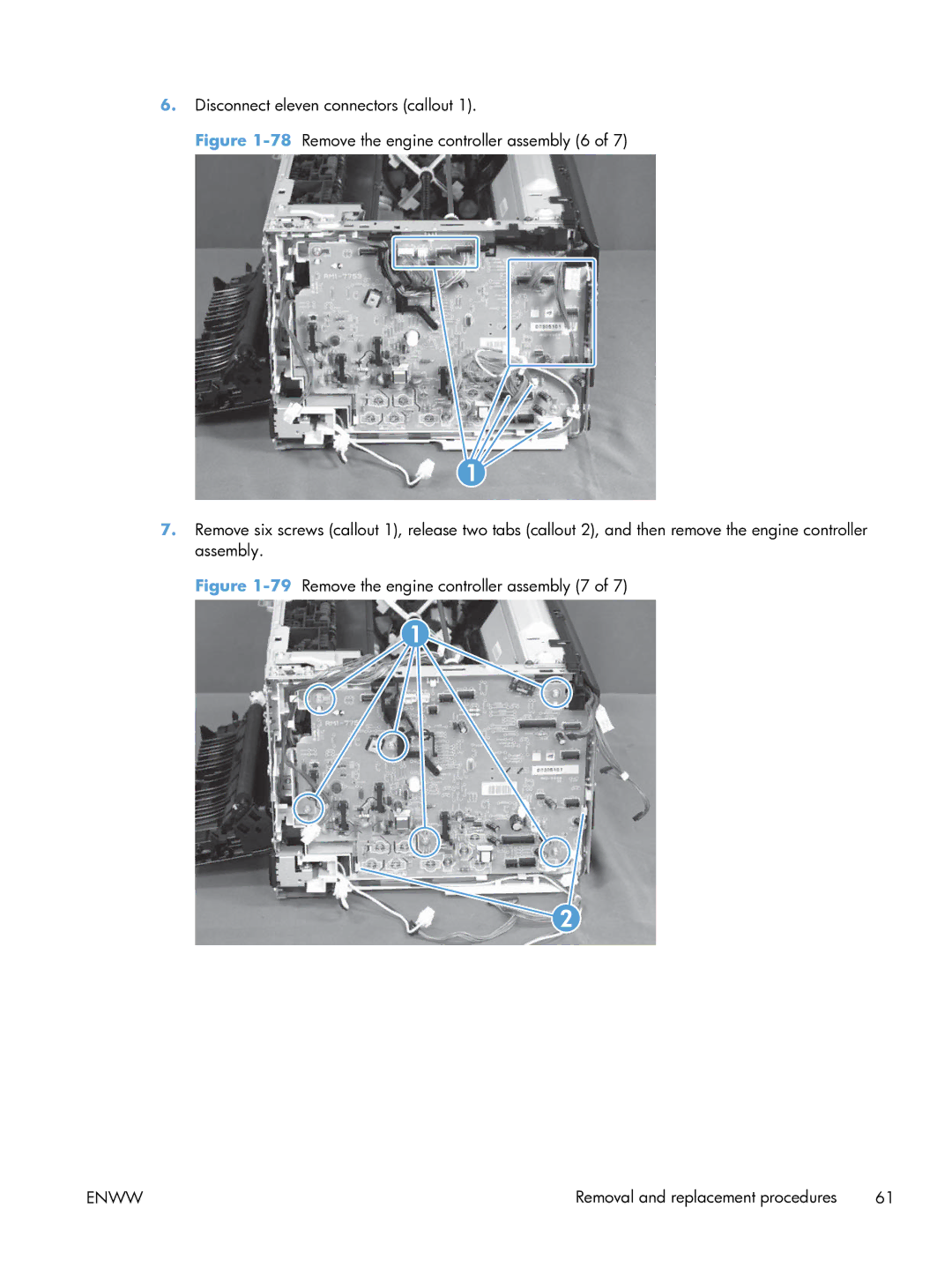
Remove the engine controller assembly
Engine controller assembly
75Remove the engine controller assembly 3
Enww
79Remove the engine controller assembly 7
Installing a replacement engine controller assembly
Remove the low-voltage power supply assembly
Low-voltage power supply assembly
Enww
85Remove the low-voltage power supply assembly 5
Enww
89Remove the low-voltage power supply assembly 9
Installing a replacement low-voltage power supply
Reinstall the low-voltage power supply
Document feeder input tray
Document feeder components
Document feeder cover
Enww
Remove the document feeder core
Document feeder core
100Remove the document feeder core 4
Remove the post scan pinch rollers
Post scan pinch rollers
Remove the document feeder base assembly
Document feeder base assembly
Enww
Solve problems
Test print functionality
Solve problems checklist
Test copy functionality
Menu map
Determine the problem source
Troubleshooting processes
Power-on checks
Power subsystem
Component diagnostics
Tools for troubleshooting
Component tests
Locations of connectors
Diagrams
2Cross section view
Locations of major components
1External covers and doors base
3External covers and doors base
Timing diagram
General timing chart
Scanner Ass’y Label
General circuit diagram
Internal print-quality test pages
Print a Diagnostics
Interpret the Print Quality
Repetitive image defects ruler
Print-quality troubleshooting tools
Calibrate the product
Reports menu
Setup menu
System Setup menu
Control panel menus
Enww
Low Threshold
Network Setup menu network models only
Service menu
Copy Menu
Function specific menus
Enww
Secondary service menu
Service mode functions
Service menu/Secondary service menu
Service menu
3Secondary service menu
Secondary service menu structure
Nvram initialization
Product updates
Product resets
Restore factory settings
Enww
Parts and diagrams
Supplies part numbers
Order parts by authorized service providers
Order replacement parts
Related documentation and software
Whole-unit replacement part numbers
Service parts
4Whole-unit replacement part numbers
How to use the parts lists and diagrams
Base product no optional trays or accessories
Assembly locations
Base product
2Covers, panels, and doors
Covers, panels, and doors
Description Part number Qty
Covers, panels, and doors
Internal assembly
Internal assembly
7Internal assembly
PCAs
PCAs
PCAs
Scanner and document feeder ADF main assemblies
Scanner and document feeder main assemblies
Document feeder internal components
6Document feeder assembly parts Parts and diagrams
Document feeder assembly parts
11Alphabetical parts list
Alphabetical parts list
Input tray, assembly ADF CE538-60122
Spring, control panel CE865-00009
12Numerical parts list
Numerical parts list
RC3-1287-000 Cover, blanking
RM1-7280-000 Right cover assembly
Enww
Service and support
HP Product Duration of Limited Warranty
Hewlett-Packard limited warranty statement
Hewlett-Packard limited warranty statement
Enww
Enww
Data stored on the print cartridge and imaging drum
End User License Agreement
Transfer
OpenSSL
Customer support
Customer self-repair warranty service
Repack the product
Enww
Specifications
Table B-1Physical specifications1
Physical specifications
Table B-2Environmental specifications
Regulatory information
FCC regulations
Declaration of conformity base models
Safety
Boise, Idaho USA
Radio
Declaration of conformity wireless models
Enww
Hewlett Packard Certificate of Volatility
Certificate of Volatility
Power cord statement Japan
Safety statements
Laser safety
Vcci statement Japan Power cord instructions
GS statement Germany
EMC statement Korea Laser statement for Finland
Enww
Additional statements for wireless products
Korean statement Taiwan statement
Macintosh
Symbols/Numerics 2ndary service menu Accessories
Network
Screwdrivers, required Screws Replacing
Page
CE865-90968* *CE865-90968