Reassembly Notes
Caution
Install new screws for all screws you remove that hold the display hinges. Otherwise, the hinges could loosen over time.
Hint
∙While attaching the LCD flex cable to the LVDS PCA, rest one corner of the display on the bottom case.
∙On the bottom case, the holes for the display screws are marked by “D”. The hole recesses have flat bottoms for the
Removing the LCD Module
(HP Authorized Service Providers Only)
Note
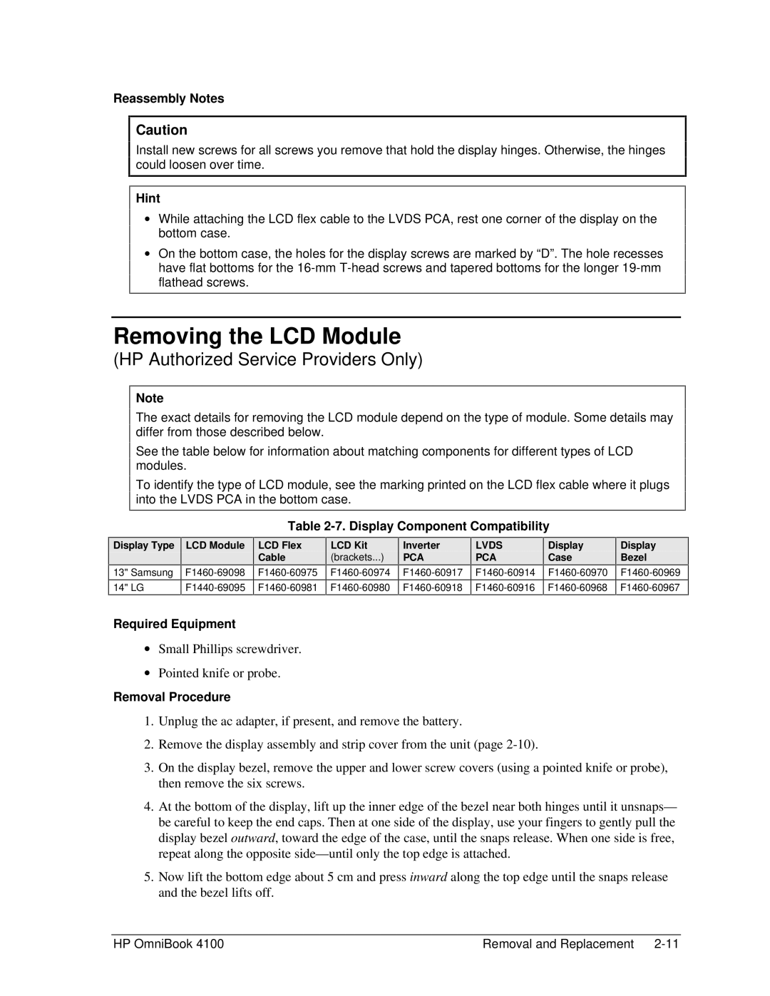
The exact details for removing the LCD module depend on the type of module. Some details may differ from those described below.
See the table below for information about matching components for different types of LCD modules.
To identify the type of LCD module, see the marking printed on the LCD flex cable where it plugs into the LVDS PCA in the bottom case.
Table 2-7. Display Component Compatibility
Display Type | LCD Module | LCD Flex | LCD Kit | Inverter | LVDS | Display |
|
| Cable | (brackets...) | PCA | PCA | Case |
|
| |||||
13" Samsung |
Display
Bezel
14" LG
Required Equipment
∙Small Phillips screwdriver.
∙Pointed knife or probe.
Removal Procedure
1.Unplug the ac adapter, if present, and remove the battery.
2.Remove the display assembly and strip cover from the unit (page
3.On the display bezel, remove the upper and lower screw covers (using a pointed knife or probe), then remove the six screws.
4.At the bottom of the display, lift up the inner edge of the bezel near both hinges until it unsnaps— be careful to keep the end caps. Then at one side of the display, use your fingers to gently pull the display bezel outward, toward the edge of the case, until the snaps release. When one side is free, repeat along the opposite
5.Now lift the bottom edge about 5 cm and press inward along the top edge until the snaps release and the bezel lifts off.
HP OmniBook 4100 | Removal and Replacement |
