HP OmniBook
Edition History
Contents
Tables
Figures
HP OmniBook
Sources of OmniBook Information
Introduction
Source
Address or Number
OmniBook 4100 Models
Product Information
OmniBook Front View
Features and Operation
Product Comparisons
Power Management Power States
OmniBook OmniBook 2100/3100 Processor Memory
Video Operating System
Turning the OmniBook On and Off
Activating Power Modes
Checking the Status of the OmniBook
Main Status Lights LED Strip Cable
Keyboard Status Lights VGA PCA
Resetting the OmniBook
Using Fn Hot Keys
Fn Hot Keys
Hot Key
System Resources
System Interrupts
System Memory
10. DMA Channels
System Input/Output Addresses 100-3FF
11. OmniBook 4100 Specifications
Specifications
Product Information HP OmniBook
12. OmniBook 4100 Accessories
OmniBook 4100-Only Accessories
OmniBook 7100, 4100, 3100, 2100 Accessories
Internal Design
Replaceable Module Diagram
Docking port
13. Functional Structure
Page
Removal Cross-Reference
Removal and Replacement
Recommended Screw Torques
Required Equipment
Screw Thread Size
Torque kgfcm Torque inlbf
Removal Procedure
Removing the Battery or Plug-In Module
Removing a RAM Board
RAM Board Replacement Part Numbers
Description Part Number
Exchange Part Number
Hard Disk Drive Replacement Part Numbers
Removing the Hard Disk Drive
Description Part Number Exchange Part Number
Creating a Hibernate Partition
Installing a Hard Drive in the Cover Reassembly Notes
Replacement Procedure
Replacing Small Parts
Replacing Small Parts User-Replaceable
Removing the Keyboard
Removing the Keyboard
Hint
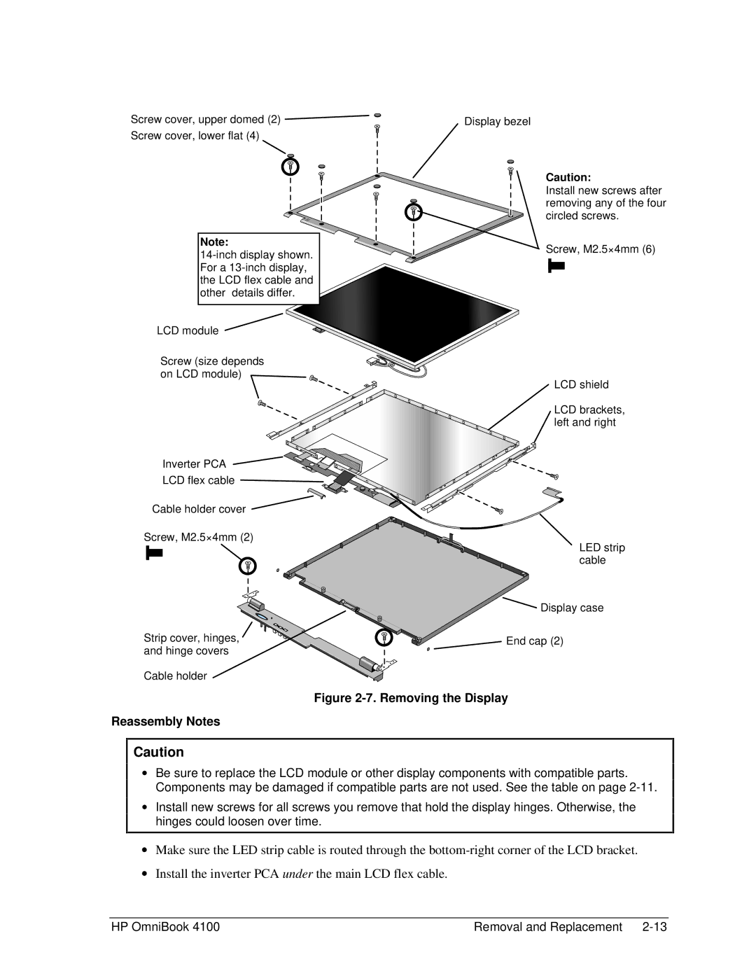
Removing the Display
Removing the Display Assembly
Display Component Compatibility
Removing the LCD Module
Removal and Replacement HP OmniBook
Removing the Display Reassembly Notes
Removing the Top Case
Removing the Top Case Reassembly Notes
Removing the Motherboard or Bottom Case
Removing the Motherboard
Reassembly Notes
Installing a New Serial Number Label
10. Installing Docking Doors and Module Latch
12. Removing the Bios IC
Removing the Bios IC
Removing Other Components
Display Bezel Display Case Removal Procedures
Removing Display Components
Component Cable Holder
Component Display Latch
10. Removing Bottom Case Components
Removing Top Case Components
Component CPU Bottom Plate CPU Module MMO CPU Top Plate
Fan Removal Procedures
IR PCA Lvds PCA
Component Frame, Left Frame, Left or Right Heatsink Parts
VGA PCA
Component Speaker, Left Speaker, Right Speaker Cover
Troubleshooting and Diagnostics
Troubleshooting the Problem
Troubleshooting
Verifying the Repair
Scope of Diagnostic Tools
Suggestions for Troubleshooting
Troubleshooting Suggestions
Symptom
Startup
Call Center Suggestions
Power/Battery
Repair Center Likely Causes
Repair Center Comments
Erratic display
Touch pad Call Center Suggestions
Pointing stick
Serial/Parallel
Symptom AC adapter
Accessories
Miscellaneous
Check module contacts. Push system-off button
Diagnostic Tools
OmniBook Diagnostic Program
Creating a Diagnostic Floppy Disk
Enter
Running the Diagnostic Test
Code Suggestions System Tests
OmniBook Diagnostic Error Codes
Hard Disk Tests
Parallel Port Tests
Post Terminal-Error Beep Codes
Power-On Self-Test
Beep Codes
Post Description
Post Messages
Message
Description
Message Description
Allocation Error for device
Sycard PCCtest 450 CardBus Card Optional
Uninstalling the DMI Package
Installing the DMI Package
Using the DMI Interface
Desktop Management Interface DMI
DMI Components
Contents of the DMI Package
Running the Bios Setup Utility
Bios Setup Utility
Bios Setup Menus and Parameters
Main Menu Default
Power Menu Default
Security Menu Default
Exit Menu
Boot Menu Default
Page
Replaceable Parts
Exploded View
User- Replaceable
OmniBook Replaceable Parts
41 PCA, DC-DC
Display Components
Motherboard Components
Accessory Replaceable Parts
Assembly-Component Breakdown
PCA, VGA PCA, IR PCA, DC-DC
Part Number Reference
Part Number Exchange Part Number
F1460-69098
Reference Information
Password Removal Policy
Reference Information HP OmniBook
Hewlett-Packard Display Quality Statement
OmniBook 4100 LCD Guidelines TFT
Page
Page
Part Number F1460-90020

 Display case