4.Install four M3 metric guide screws in the lower holes on each side of the drive. HP has provided four extra M3 metric guide screws on the front of the chassis, under the front bezel. The M3 metric guide screws are black. Refer to Installing and Removing Drives on page 109 for an illustration of the extra M3 metric guide screws location.
![]()
![]()
![]()
![]() NOTE: When replacing the drive, transfer the four M3 metric guide screws from the old drive to the new one.
NOTE: When replacing the drive, transfer the four M3 metric guide screws from the old drive to the new one.
CAUTION: Use only
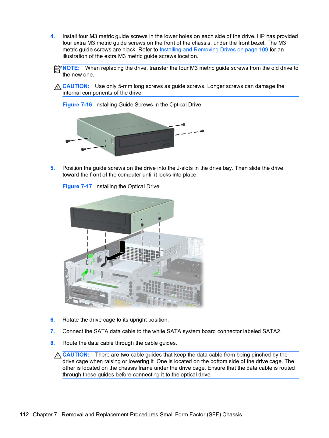
Figure 7-16 Installing Guide Screws in the Optical Drive
5.Position the guide screws on the drive into the J-slots in the drive bay. Then slide the drive toward the front of the computer until it locks into place.
Figure 7-17 Installing the Optical Drive
6.Rotate the drive cage to its upright position.
7.Connect the SATA data cable to the white SATA system board connector labeled SATA2.
8.Route the data cable through the cable guides.
CAUTION: There are two cable guides that keep the data cable from being pinched by the drive cage when raising or lowering it. One is located on the bottom side of the drive cage. The other is located on the chassis frame under the drive cage. Ensure that the data cable is routed through these guides before connecting it to the optical drive.