System Board Connections
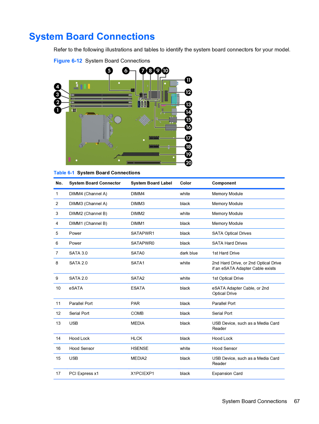
Refer to the following illustrations and tables to identify the system board connectors for your model.
Figure 6-12 System Board Connections
Table 6-1 System Board Connections
No. | System Board Connector | System Board Label | Color | Component |
|
|
|
|
|
1 | DIMM4 (Channel A) | DIMM4 | white | Memory Module |
|
|
|
|
|
2 | DIMM3 (Channel A) | DIMM3 | black | Memory Module |
|
|
|
|
|
3 | DIMM2 (Channel B) | DIMM2 | white | Memory Module |
|
|
|
|
|
4 | DIMM1 (Channel B) | DIMM1 | black | Memory Module |
|
|
|
|
|
5 | Power | SATAPWR1 | black | SATA Optical Drives |
|
|
|
|
|
6 | Power | SATAPWR0 | black | SATA Hard Drives |
|
|
|
|
|
7 | SATA 3.0 | SATA0 | dark blue | 1st Hard Drive |
|
|
|
|
|
8 | SATA 2.0 | SATA1 | white | 2nd Hard Drive, or 2nd Optical Drive |
|
|
|
| if an eSATA Adapter Cable exists |
|
|
|
|
|
9 | SATA 2.0 | SATA2 | white | 1st Optical Drive |
|
|
|
|
|
10 | eSATA | ESATA | black | eSATA Adapter Cable, or 2nd |
|
|
|
| Optical Drive |
|
|
|
|
|
11 | Parallel Port | PAR | black | Parallel Port |
|
|
|
|
|
12 | Serial Port | COMB | black | Serial Port |
|
|
|
|
|
13 | USB | MEDIA | black | USB Device, such as a Media Card |
|
|
|
| Reader |
|
|
|
|
|
14 | Hood Lock | HLCK | black | Hood Lock |
|
|
|
|
|
16 | Hood Sensor | HSENSE | white | Hood Sensor |
|
|
|
|
|
15 | USB | MEDIA2 | black | USB Device, such as a Media Card |
|
|
|
| Reader |
|
|
|
|
|
17 | PCI Express x1 | X1PCIEXP1 | black | Expansion Card |
|
|
|
|
|
System Board Connections 67