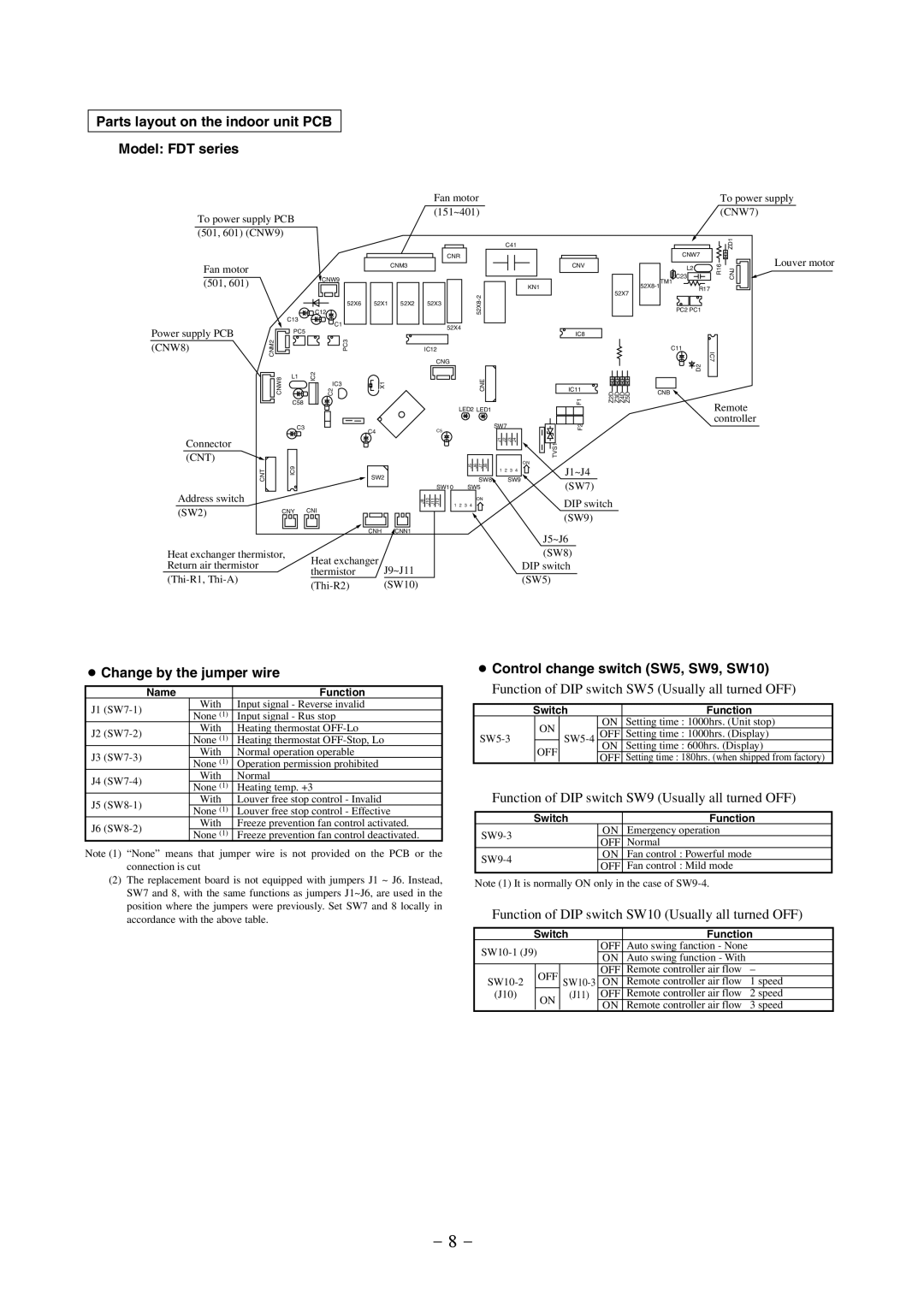
Parts layout on the indoor unit PCB
Model: FDT series
|
|
|
|
|
|
| Fan motor |
|
|
|
|
| ||
To power supply PCB |
|
|
|
| (151~401) |
|
|
|
|
| ||||
|
|
|
|
|
|
|
|
|
|
|
| |||
(501, 601) (CNW9) |
|
|
|
|
|
|
|
|
|
|
|
| ||
|
|
|
|
|
|
|
|
|
| C41 |
|
| ||
|
|
|
|
|
|
|
| CNR |
|
|
|
|
|
|
Fan motor |
|
|
|
|
| CNM3 |
|
|
|
|
|
| CNV |
|
|
|
|
|
|
|
|
|
|
|
|
|
|
| |
(501, 601) |
|
|
| CNW9 |
|
|
|
|
|
|
|
|
|
|
|
|
|
|
|
|
|
|
|
|
|
| KN1 | 52X7 | |
|
|
|
|
|
|
|
|
|
|
|
|
| ||
|
|
| C12 |
|
|
|
|
|
|
|
|
| ||
|
|
| 52X1 | 52X2 | 52X3 |
| 52X8 |
|
|
|
|
| ||
|
|
|
| 52X6 |
|
|
|
|
|
|
| |||
|
| C13 |
| C1 |
|
|
|
|
|
|
|
|
|
|
Power supply PCB |
|
|
|
|
|
| 52X4 |
|
|
|
|
|
| |
| PC5 |
|
|
|
|
|
|
|
|
| IC8 |
| ||
|
|
|
|
|
|
|
|
|
|
|
| |||
CNM2 |
|
| PC3 |
|
|
|
|
|
|
|
|
| ||
(CNW8) |
|
|
|
| IC12 |
|
|
|
|
|
|
| ||
|
|
|
|
|
|
|
|
|
|
|
|
| ||
| CNW8 |
|
|
|
|
| CNG | CNE |
|
|
|
| Z2D Z3D Z4D Z5D | |
| C58 | IC2 | C2 | X1 |
|
|
|
|
|
| F1 | |||
|
| L1 |
|
|
|
|
|
|
|
|
|
|
|
|
|
|
|
| IC3 |
|
|
|
|
|
|
|
| IC11 |
|
|
|
|
|
|
|
|
|
|
|
|
|
|
| |
|
|
|
|
|
|
|
| LED2 LED1 |
|
|
|
|
| |
|
| C3 |
|
| C4 |
| C5 |
| SW7 |
|
| F2 |
| |
|
|
|
|
|
|
|
|
|
|
|
|
| ||
Connector |
|
|
|
|
|
|
|
| J1 | J2 | J3 | J4 | TVS1 |
|
|
|
|
|
|
|
|
|
|
|
|
|
| ||
(CNT) |
|
|
|
|
|
|
|
|
|
|
|
|
| |
|
|
|
|
|
|
|
| J5J6J7SW8J8 |
|
|
| ON |
| |
| CNT | IC9 |
|
| SW2 |
|
|
|
| SW9 |
| |||
|
|
|
|
|
| 2 | J1~J4 |
| ||||||
|
|
|
|
|
|
|
|
| 1 | 3 | 4 |
|
| |
Address switch |
|
|
|
|
|
| SW10 | SW5 |
|
|
| (SW7) |
| |
|
|
|
|
|
| J8 J10 J11 J12 |
| ON |
|
|
| DIP switch | ||
(SW2) |
| CNY | CNI |
|
|
|
| 1 2 | 3 4 |
|
|
| ||
|
|
|
|
|
|
|
|
|
| (SW9) |
| |||
|
|
|
|
|
|
|
|
|
|
|
|
|
| |
|
|
|
|
| CNH | CNN1 |
|
|
|
|
|
| J5~J6 |
|
|
|
|
|
|
|
|
|
|
|
|
|
|
| |
Heat exchanger thermistor, | Heat exchanger |
|
|
|
|
|
|
| (SW8) |
| ||||
Return air thermistor |
|
|
|
|
|
|
|
|
| DIP switch |
| |||
|
| thermistor | J9~J11 |
|
|
|
|
|
|
| ||||
|
|
|
|
|
|
|
| (SW5) |
| |||||
|
| (SW10) |
|
|
|
|
|
|
| |||||
|
|
|
|
|
|
|
|
|
|
| ||||
To power supply (CNW7)
|
|
| ZD1 |
| CNW7 |
| Louver motor |
| C23 | R16 | |
| CNJ | ||
| L2 |
|
|
TM1 |
|
| |
R17 |
|
| |
|
|
| |
| PC2 PC1 |
|
|
| C11 | IC7 |
|
| D2 |
| |
|
|
|
CNB ![]()
Remote controller
●Change by the jumper wire
| Name | Function | |
J1 |
| With | Input signal - Reverse invalid |
| None (1) | Input signal - Rus stop | |
|
| ||
J2 |
| With | Heating thermostat |
| None (1) | Heating thermostat | |
|
| ||
J3 |
| With | Normal operation operable |
| None (1) | Operation permission prohibited | |
|
| ||
J4 |
| With | Normal |
| None (1) | Heating temp. +3 | |
|
| ||
J5 |
| With | Louver free stop control - Invalid |
| None (1) | Louver free stop control - Effective | |
|
| ||
J6 |
| With | Freeze prevention fan control activated. |
| None (1) | Freeze prevention fan control deactivated. | |
|
| ||
Note (1) “None” means that jumper wire is not provided on the PCB or the connection is cut
(2)The replacement board is not equipped with jumpers J1 ~ J6. Instead, SW7 and 8, with the same functions as jumpers J1~J6, are used in the position where the jumpers were previously. Set SW7 and 8 locally in accordance with the above table.
●Control change switch (SW5, SW9, SW10)
Function of DIP switch SW5 (Usually all turned OFF)
| Switch |
| Function | ||
| ON |
| ON | Setting time : 1000hrs. (Unit stop) | |
OFF | Setting time : 1000hrs. (Display) | ||||
| |||||
OFF | ON | Setting time : 600hrs. (Display) | |||
|
| ||||
|
| OFF | Setting time : 180hrs. (when shipped from factory) | ||
|
|
| |||
Function of DIP switch SW9 (Usually all turned OFF)
| Switch | Function | |
| ON | Emergency operation | |
| OFF | Normal | |
|
| ||
| ON | Fan control : Powerful mode | |
| OFF | Fan control : Mild mode | |
|
| ||
Note (1) It is normally ON only in the case of
Function of DIP switch SW10 (Usually all turned OFF)
| Switch |
|
| Function | ||
| OFF | Auto swing fanction - None |
| |||
| ON | Auto swing function - With |
| |||
|
|
|
|
| ||
| OFF |
|
| OFF | Remote controller air flow | – |
ON | Remote controller air flow | 1 speed | ||||
(J10) | ON |
| (J11) | OFF | Remote controller air flow | 2 speed |
|
|
| ON | Remote controller air flow | 3 speed | |
|
|
|
| |||
- 8 -