3.Check display on wireless specification models (FDTN · FDEN · FDKN)
(1)Indication board
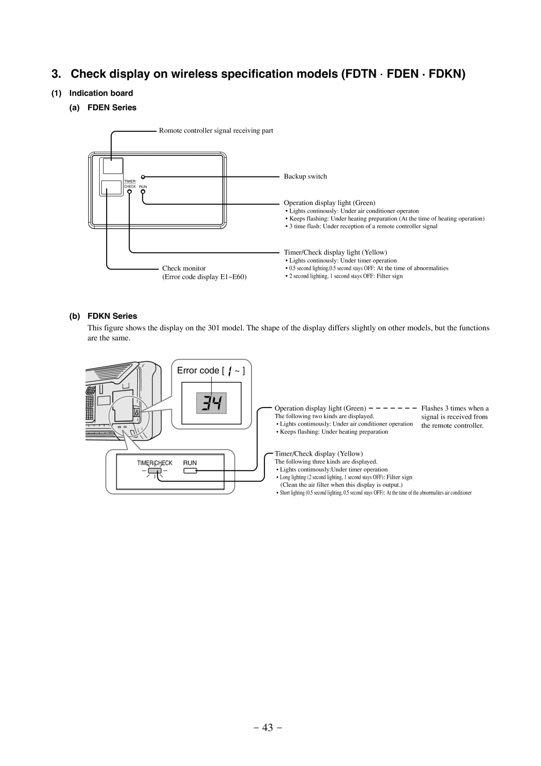
(a)FDEN Series
TIMER
CHECK
Romote controller signal receiving part
Backup switch
RUN
Operation display light (Green)
•Lights continously: Under air conditioner operaton
•Keeps flashing: Under heating preparation (At the time of heating operation)
•3 time flash: Under reception of a remote controller signal
| Timer/Check display light (Yellow) |
| • Lights continously: Under timer operation |
Check monitor | • 0.5 second lighting,0.5 second stays OFF: At the time of abnormalities |
(Error code display E1~E60) | • 2 second lighting, 1 second stays OFF: Filter sign |
(b)FDKN Series
This figure shows the display on the 301 model. The shape of the display differs slightly on other models, but the functions are the same.
Error code [  ~ ]
~ ]
TIMER/CHECK RUN
Operation display light (Green) | Flashes 3 times when a |
The following two kinds are displayed. | signal is received from |
• Lights contimously: Under air conditioner operation | the remote controller. |
• Keeps flashing: Under heating preparation |
|
Timer/Check display (Yellow)
The following three kinds are displayed.
•Lights contimously:Under timer operation
•Long lighting (2 second lighting, 1 second stays OFF): Filter sign (Clean the air filter when this display is output.)
•Short lighting (0.5 second lighting, 0.5 second stays OFF): At the time of the abnormalites air conditioner
- 43 -