2
Error display “![]()
![]()
![]() WAIT
WAIT ![]()
![]()
![]() ”
”
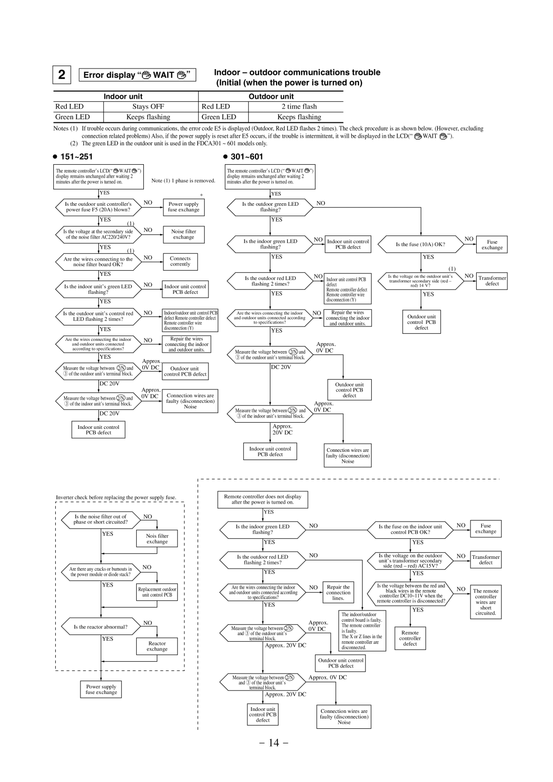
Indoor – outdoor communications trouble (Initial (when the power is turned on)
| Indoor unit |
| Outdoor unit |
Red LED | Stays OFF | Red LED | 2 time flash |
|
|
|
|
Green LED | Keeps flashing | Green LED | Keeps flashing |
|
|
|
|
Notes (1) If trouble occurs during communications, the error code E5 is displayed (Outdoor, Red LED flashes 2 times). The check procedure is as shown below. (However, excluding
connection related problems) Also, if the power supply is reset after E5 occurs, if the trouble is intermittent, it will be displayed in the LCD(“ ![]()
![]()
![]() WAIT
WAIT ![]()
![]()
![]() ”).
”).
(2) The green LED in the outdoor unit is used in the FDCA301 ~ 601 models only.
● 151~251 | ● 301~601 |
The remote controller’s LCD(“ ![]()
![]() WAIT
WAIT ![]()
![]() ”) display remains unchanged after waiting 2 minutes after the power is turned on.
”) display remains unchanged after waiting 2 minutes after the power is turned on.
YES
Is the outdoor unit controller's power fuse F5 (20A) blown?
YES
(1)
Note (1) 1 phase is removed.
*
NO |
| Power supply |
|
| fuse exchange |
|
|
|
The remote controller’s LCD (“ ![]()
![]() WAIT
WAIT ![]()
![]() ”) display remains unchanged after waiting 2 minutes after the power is turned on.
”) display remains unchanged after waiting 2 minutes after the power is turned on.
| YES |
|
Is the outdoor green LED | NO | |
flashing? |
| |
YES
Is the voltage at the secondary side of the noise filter AC220/240V?
YES
(1)
NO |
| Noise filter |
|
| exchange |
|
|
|
Is the indoor green LED
flashing?
NO Indoor unit control PCB defect
NO
Is the fuse (10A) OK? ![]() Fuse exchange
Fuse exchange
Are the wires connecting to the
noise filter board OK?
YES
Is the indoor unit’s green LED
flashing?
YES
Is the outdoor unit’s control red
LED flashing 2 times?
YES
Are the wires connecting the indoor
and outdoor units connected according to specifications?
YES
Measure the voltage between 2/N and
3of the outdoor unit’s terminal block. DC 20V
Measure the voltage between 2/N and
3of the indoor unit’s terminal block. DC 20V
Indoor unit control
PCB defect
NO |
|
|
| Connects |
|
NO |
|
|
| corrently |
|
|
|
|
|
| |
|
|
| Indoor unit control | ||
|
|
|
| PCB defect | |
NO |
|
|
| Indoor/outdoor unit control PCB | |
|
|
|
| defect Remote controller defect | |
|
| ||||
|
|
|
| Remote controller wire | |
|
|
|
| disconnection (Y) | |
NO |
|
|
| Repair the wires | |
|
|
|
| connecting the indoor | |
| |||||
|
|
|
| and outdoor units. | |
Approx.
0V DC Outdoor unit control PCB defect
Approx.
0V DC Connection wires are ![]() faulty (disconnection)
faulty (disconnection)
Noise
YES
Is the outdoor red LED
flashing 2 times?
YES
Are the wires connecting the indoor and outdoor units connected according to specifications?
YES
Measure the voltage between 2/N and
3of the outdoor unit’s terminal block. DC 20V
Measure the voltage between 2/N and
3of the indoor unit’s terminal block.
Approx. 20V DC
Indoor unit control
PCB defect
NO Indoor unit control PCB defect
Remote controller defect Remote controller wire disconnection (Y)
NO Repair the wires ![]() connecting the indoor
connecting the indoor
and outdoor units.
Approx. 0V DC
Outdoor unit control PCB defect
Approx. 0V DC
Connection wires are faulty (disconnection)
Noise
YES
(1)
Is the voltage on the outdoor unit’s | NO | Transformer |
transformer secondary side (red – |
| |
| defect | |
red) 14 V? |
| |
|
|
YES
Outdoor unit control PCB defect
Inverter check before replacing the power supply fuse.
Is the noise filter out of | NO | ||
phase or short circuited? |
|
| |
|
|
|
|
YES |
| Nois filter | |
|
| ||
|
| exchange | |
|
|
|
|
Remote controller does not display
after the power is turned on.
YES
Is the indoor green LED
flashing?
YES
NO
Is the fuse on the indoor unit | NO | Fuse |
control PCB OK? |
| exchange |
YES
Are there any cracks or burnouts in | NO |
the power module or diode stack? |
|
|
|
YES
Replacement outdoor
unit control PCB
Is the outdoor red LED | NO |
| Is the voltage on the outdoor | NO | Transformer |
flashing 2 times? |
|
| unit’s transformer secondary |
| defect |
|
| side (red – red) AC15V? |
| ||
YES |
|
|
|
| |
|
| YES |
|
| |
Are the wires connecting the indoor | NO | Repair the | Is the voltage between the red and | NO |
|
and outdoor units connected according |
| connection | black wires in the remote |
| The remote |
to specifications? |
| lines. | controller DC10~11V when the |
| controller |
YES |
|
| remote controller is disconnected? |
| wires are |
|
| YES |
| short | |
|
|
|
| ||
|
| The indoor/outdoor |
| circuited. | |
|
|
|
| ||
|
| control board is faulty. |
|
| |
Is the reactor abnormal?
YES
Power supply fuse exchange
NO
Reactor
exchange
Measure the voltage between 2/N | Approx. | The remote controller |
| ||
0V DC |
| ||||
is faulty. | Remote | ||||
and 3 of the outdoor unit’s |
|
| |||
terminal block. |
| The X or Z lines in the | controller | ||
| remote controller are | ||||
Approx. 20V DC |
| defect | |||
| disconnected. | ||||
|
|
|
| ||
|
|
|
|
| |
|
| Outdoor unit control | ||
|
| PCB defect | ||
Measure the voltage between 2/N | Approx. 0V DC | |||
and 3 of the indoor unit’s |
|
|
| |
terminal block. |
|
| ||
Approx. 20V DC |
|
| ||
Indoor unit |
|
| ||
Connection wires are | ||||
control PCB | ||||
faulty (disconnection) | ||||
defect | ||||
| Noise | |||
|
|
| ||
- 14 -