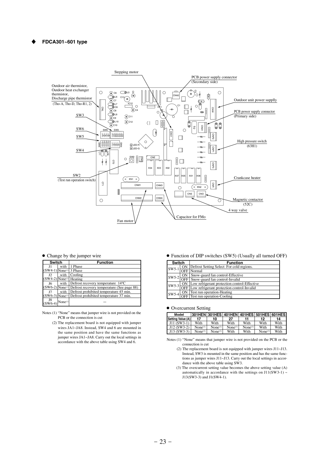
SFDCA301~601 type
Outdoor air thermistor, Outdoor heat exchanger thermistor,
Discharge pipe thermistor
SW3
SW6
SW5
SW4
CNL |
|
|
|
|
SW6 |
| |||
J5 | J6 | J7 | J8 | |
1 | 2 | 3 | 4 | |
SW5 |
|
|
|
|
L11 |
|
| L12 | |
Stepping motor
C6 |
|
| L5 | C5 |
| ||
| L6 |
| C13 |
|
| ||
C7 |
|
|
|
|
|
| |
| L7 |
|
| IC12 |
| ||
|
|
|
|
|
| ||
| C6 |
|
|
|
|
| |
C8 |
|
|
|
| C4 |
| |
|
|
|
|
|
| ||
| L8 |
|
| C11 |
| ||
C9 |
|
|
|
| |||
|
|
|
|
|
| ||
| L10 |
| C12 |
| |||
C10 |
|
|
|
|
| ||
| SW3 |
|
|
|
| ||
J11 | J12 | J13 | J14 | J15 | J16 |
|
|
J1 | J2 | J3 | J4 | SW4 |
|
| |
|
|
|
|
|
|
| |
|
|
|
|
|
| SW2 | CNQ |
CT2 |
|
|
|
|
| ||
PCB power supply connector (Secondary side)
|
|
| C3 |
|
|
|
| CNA2 |
|
|
|
|
| Outdoor unit power supplly |
| HT1 |
| C1 |
|
|
| CNW |
| |
| C2 |
| PCB power supply connector | |
|
|
| ||
|
|
|
| |
|
|
|
| (Primary side) |
|
| CNV1 | CNA1 |
|
|
| CNP2 | High pressure switch | |
|
|
|
| |
|
|
| CNP1 | (63H1) |
|
|
|
| |
CNE |
|
|
|
|
X04 | X03 | X02 | CNP3 |
|
|
|
SW2
(Test run operation switch) | KN1 |
CT1 | CNM1 |
| CNM2 |
| Fan motor |
X07 | X05 | X01 | X06 | Crankcase heater |
|
|
|
| |
CNM3 |
|
| KN2 | CNR |
|
|
| ||
|
|
|
| |
|
| CNS | CNO |
|
CNM4 |
|
|
| Magnetic contactor |
|
|
|
| |
|
|
|
| (52C) |
|
|
|
| 4 way valve |
Capacitor for FMo |
| |||
●Change by the jumper wire
Switch | Function | |
J1 | with | 1 Phase |
None(1) | 3 Phase | |
J2 | with | Cooling |
None(1) | Heating | |
J6 | with | Defrost recovery temperature 14ºC |
None(1) | Defrost recovery temperature (See page 88) | |
J7 | with | Defrost prohibited temperature 45 min. |
None(1) | Defrost prohibited temperature 37 min. | |
J8 | None(1) | - |
Notes (1) “None” means that jumper wire is not provided on the PCB or the connection is cut
(2)The replacement board is not equipped with jumper wires JA1~JA8. Instead, SW4 and 6 are mounted in the same position and have the same functions as jumper wires JA1~JA8. Carry out the local settings in accordance with the above table using SW4 and 6.
●Function of DIP switches (SW5) (Usually all turned OFF)
Switch | Function | |
ON | Defrost Setting Select For cold regions. | |
OFF | Normal | |
ON | ||
OFF | ||
ON | Low refrigerant protection | |
OFF | Low refrigerant protection | |
ON | Test run | |
OFF | Test run | |
●Overcurrent Setting
Model | 301HEN | 301HES | 401HEN | 401HES | 501HES | 601HES |
Setting Value (A) | 17 | 10 | 27 | 11 | 12 | 14 |
J11 | With | With | With | With | With | With |
J12 | None(1) | None(1) | None(1) | None(1) | With | With |
J13 | None(1) | None(1) | With | With | None(1) | With |
Notes (1) “None” means that jumper wire is not provided on the PCB or the connection is cut
(2)The replacement board is not equipped with jumper wires J11~J13. Instead, SW3 is mounted in the same position and has the same func- tions as jumper wires J11~J13. Carry out the local settings in accor- dance with the above table using SW3.
(3)The overcurrent setting value becomes the above setting value (A) automatically in accordance with the settings on
- 23 -