Manuals
/
Husqvarna
/
Lawn and Garden
/
Lawn Mower
Husqvarna
ProFlex 18
manual
Lubrication chart
Models:
ProFlex 18
1
46
68
68
Download
68 pages
1.83 Kb
43
44
45
46
47
48
49
50
Troubleshooting
Belt diagram
Explanation of Symbols
Adjusting the hydrostatic wire
Maintenance
Adjusting the brakes
Cleaning the pulse air filter
Belt replacement on BioClip
Safety
Service
Page 46
Image 46
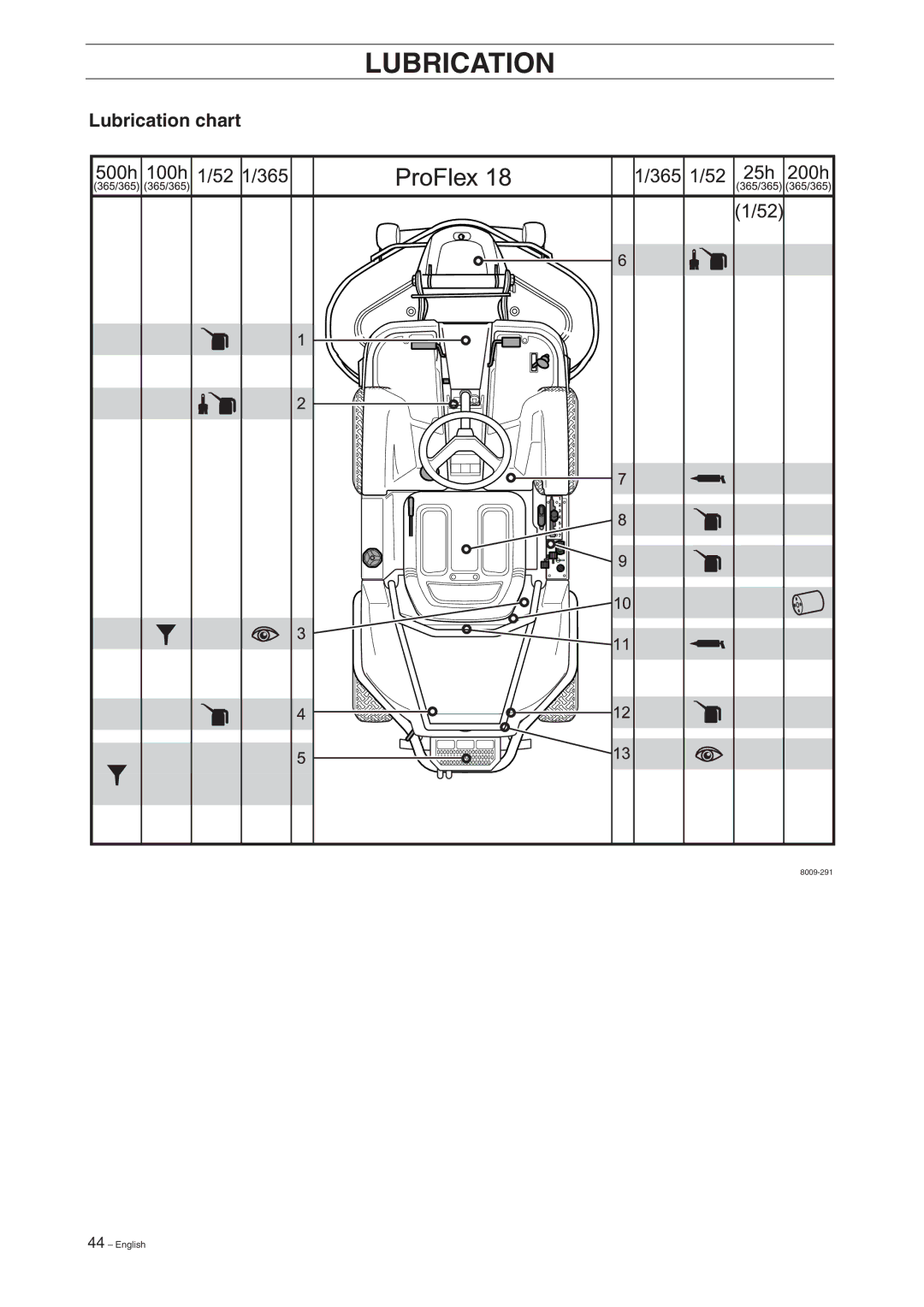
LUBRICATION
Lubrication chart
8009-291
44
– English
Page 45
Page 47
Page 46
Image 46
Page 45
Page 47
Contents
Rider ProFlex
English
Svenska
Contents
Travel and transport on public roads
Instruction
Dear customer
Towing
Good service
Safety Instructions
Serial number
Explanation of Symbols
Read the instructions
Safety instructions
General use
Keep children away from the area to be mowed
Driving on slopes
Proceed as follows
Maintenance
Children
Do not smoke when carrying out maintenance
Transport
Never run the machine in an enclosed area
Presentation
Presentation
Location of the controls
Speed limiter
Throttle control
Choke lever
Speed of the machine is steplessly regulated
Cutting unit
Lift lever for cutting unit
Seat
Lever for adjustment of the cutting height
Parking brake
Fuelling
Before starting
Driving
Starting the engine
Driving the machine
6007-210
Cutting tips
MAX
Stopping the engine
Disengage lever
Maintenance schedule
Maintenance
Year
Hours Before after
Year 100 300
Nose
Dismantling of the machine hoods
Engine hood
Right-hand fender
Left-hand fender
Check the engine’s cooling air intake
Check the transmission’s air intake
Transmission cover
Checking and adjustment of the steering wires
Checking and adjustment of the throttle wire
Checking and adjusting the choke wire
Adjusting the hydrostatic wire
Poorly adjusted brakes can result in reduced braking power
Adjusting the brakes
Checking the tyre pressure
Replacing the air filter
Cleaning the pulse air filter
Replacement of the fuel filter
Checking of the fuel pump’s air filter
Procedures on contact with acid
Check the level of the battery acid
Fitting the wrong spark plug type can damage the engine
Inspecting the safety system
Fitting the cutting unit
Take care. Risk of crushing injury
Watch your fingers. Do not turn the blades or belt
Belt diagram
Check that the belt is fitted around the tension roller
Parallelism
Cutting height
Replacing the break-pin BioClip
Releasing from the service position
Service position for the cutting unit
Placing in the service position
Checking the blades
Dismantling the cutting unit
8009-169
Removing the attachment frame
Dismantling the belt
Assembling the belt
Belt replacement on BioClip
Replacing the cutting unit’s belts
Belt replacement on BioClip112
Removal of BioClip plug Combi
Cutting unit models
Lubrication chart
Lubrication
General
Lubricating wires
Pedal mechanism in frame tunnel
Chains in frame tunnel
Engine oil
Gear lever
Transmission
Triangular link
Throttle and choke wires, lever bearings
Driver’s seat
Belt tensioner
Oil filter, replacement
Parking brake wire
Transmission oil level
Trouble Shooting Schedule
Problem Procedure
Storage
Service
Winter storage
Wiring Diagram
Technical Data
Rider ProFlex
Rear ejector Combi
Rear ejector BioClip
EU-DECLARATION of Conformity
EU declaration of conformity Only applies to Europe
After first 8 hours
Servicejournal
Pre-delivery service
Work done
Hour service
Servicejournal
100/200 hour service
Servicejournal
At least once a season
Work done Date, mileage, stamp, sign
Servicejournal
´+H%,¶6c¨
English
114 00
Top
Page
Image
Contents