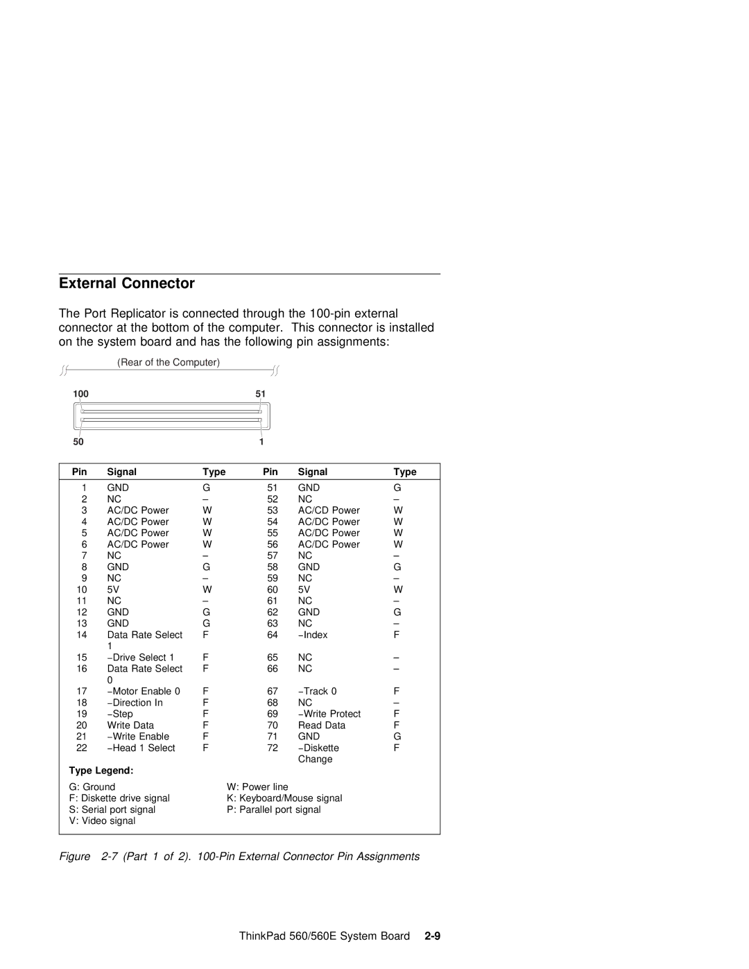
External Connector
The Port Replicator is connected through the
connector | at | the | bottom | of | the | computer. | This | connector is installed | ||||||||||||||
on | the system | board | and |
| has | the | following | pin | assignments: | |||||||||||||
|
|
|
| (Rear of the Computer) |
|
|
|
|
|
|
|
|
|
|
|
| ||||||
|
|
|
|
|
|
|
|
|
|
|
|
|
|
|
|
|
|
| ||||
100 |
|
|
|
|
|
|
| 51 |
|
|
|
|
|
|
|
|
| |||||
|
|
|
|
|
|
|
|
|
|
|
|
|
|
|
|
|
|
|
|
|
| |
|
|
|
|
|
|
|
|
|
|
|
|
|
|
|
|
|
|
|
|
|
|
|
|
|
|
|
|
|
|
|
|
|
|
|
|
|
|
|
|
|
|
|
| ||
50 |
|
|
|
|
|
|
|
| 1 |
|
|
|
|
|
|
|
|
| ||||
|
|
|
|
|
|
|
|
|
|
|
|
|
|
|
|
|
|
|
| |||
| Pin |
|
| Signal |
|
|
| Type | Pin |
|
| Signal |
|
|
|
| Type |
|
| |||
|
|
|
|
|
|
|
|
|
|
|
|
|
|
|
|
|
|
|
| |||
|
| 1 | GND |
|
|
|
| G |
| 51 |
|
| GND |
|
|
| G |
|
| |||
|
| 2 | NC |
|
|
|
| – |
| 52 |
|
| NC |
|
|
| – |
|
| |||
|
| 3 | AC/DC | Power |
| W |
| 53 |
|
| AC/CD |
| Power | W |
|
| ||||||
|
| 4 | AC/DC | Power |
| W |
| 54 |
|
| AC/DC |
| Power | W |
|
| ||||||
|
| 5 | AC/DC | Power |
| W |
| 55 |
| AC/DC | Power | W |
|
| ||||||||
|
| 6 | AC/DC | Power |
| W |
| 56 |
| AC/DC | Power | W |
|
| ||||||||
|
| 7 | NC |
|
|
|
| – |
| 57 |
|
| NC |
|
|
|
| – |
|
| ||
|
| 8 | GND |
|
|
|
| G |
| 58 |
|
| GND |
|
|
| G |
|
| |||
|
| 9 | NC |
|
|
|
| – |
| 59 |
|
| NC |
|
|
|
| – |
|
| ||
10 | 5V |
|
|
|
| W |
| 60 |
| 5V |
|
|
| W |
|
| ||||||
11 | NC |
|
|
|
| – |
| 61 |
|
| NC |
|
|
| – |
|
| |||||
12 | GND |
|
|
|
| G |
| 62 |
|
| GND |
|
|
| G |
|
| |||||
13 | GND |
|
|
|
| G |
| 63 |
|
| NC |
|
|
| – |
|
| |||||
14 | Data | Rate | SelectF |
| 64 |
|
| −Index |
| F |
|
| ||||||||||
|
|
|
| 1 |
|
|
|
|
|
|
|
|
|
|
|
|
|
|
|
|
|
|
15 | −Drive | Select | 1 | F |
|
|
|
|
| 65 | NC |
|
| – |
|
| ||||||
16 | Data | Rate | SelectF |
| 66 |
|
| NC |
|
|
| – |
|
| ||||||||
|
|
|
| 0 |
|
|
|
|
|
|
|
|
|
|
|
|
|
|
|
|
|
|
17 | −Motor | Enable 0 | F |
| 67 | −Track | 0 | F |
|
| ||||||||||||
18 | −Direction | In |
| F |
|
|
|
| 68 | NC |
|
| – |
|
| |||||||
19 | −Step |
|
|
| F |
| 69 |
|
| −Write | Protect | F |
|
| ||||||||
20 | Write | Data |
|
| F |
|
|
|
| 70 | Read | Data | F |
|
| |||||||
21 | −Write | Enable |
| F |
|
|
|
| 71 | GND |
| G |
|
| ||||||||
22 | −Head | 1 Select | F |
|
|
|
|
| 72−Diskette | F |
|
| ||||||||||
| Type | Legend: |
|
|
|
|
|
|
|
|
|
|
| Change |
|
|
|
| ||||
|
|
|
|
|
|
|
|
|
|
|
|
|
|
|
|
|
|
| ||||
| G: |
| Ground |
|
|
|
|
| W: | Power | line |
|
|
|
|
|
| |||||
| F: |
| Diskette | drive | signal |
|
|
| K: | Keyboard/Mouse signal |
|
| ||||||||||
| S: |
| Serial | port | signal |
|
|
| P: | Parallel | port signal |
|
|
| ||||||||
V:Video signal
Figure 2-7 (Part 1 of 2). 100-Pin External Connector Pin Assignments
ThinkPad 560/560E System Board