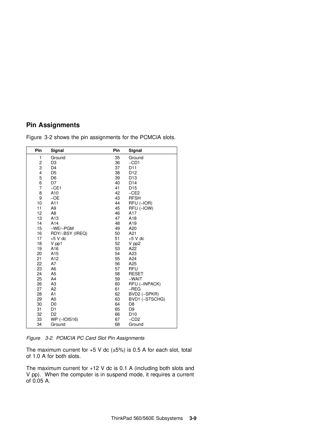
Pin Assignments
Figure | shows | the | pin |
| assignments | for | the | PCMCIA slots. |
| ||||||||||||
|
|
|
|
|
|
|
|
|
|
|
|
|
|
|
|
|
|
|
| ||
Pin | Signal |
|
|
|
| Pin |
|
| Signal |
|
|
|
|
|
|
|
|
|
| ||
|
|
|
|
|
|
|
|
|
|
|
|
|
|
|
|
|
| ||||
| 1 | Ground |
|
|
|
|
| 35 | Ground |
|
|
|
|
|
|
|
| ||||
| 2 | D3 |
|
|
|
|
|
| 36 | −CD1 |
|
|
|
|
|
|
|
|
| ||
| 3 | D4 |
|
|
|
|
|
| 37 | D11 |
|
|
|
|
|
|
|
|
| ||
| 4 | D5 |
|
|
|
|
|
| 38 | D12 |
|
|
|
|
|
|
|
|
| ||
| 5 | D6 |
|
|
|
|
|
|
| 39 | D13 |
|
|
|
|
|
|
|
|
| |
| 6 | D7 |
|
|
|
|
|
|
| 40 | D14 |
|
|
|
|
|
|
|
|
| |
| 7 | −CE1 |
|
|
|
|
|
| 41 | D15 |
|
|
|
|
|
|
|
|
|
| |
| 8 | A10 |
|
|
|
|
|
| 42 | −CE2 |
|
|
|
|
|
|
|
|
| ||
| 9 | −OE |
|
|
|
|
|
| 43 | RFSH |
|
|
|
|
|
|
|
|
|
| |
| 10 | A11 |
|
|
|
|
|
| 44 | RFU | −(IOR) |
|
|
|
|
|
|
| |||
| 11 | A9 |
|
|
|
|
|
| 45 | RFU | −(IOW) |
|
|
|
|
|
|
| |||
| 12 | A8 |
|
|
|
|
|
| 46 | A17 |
|
|
|
|
|
|
|
|
|
| |
| 13 | A13 |
|
|
|
|
| 47 | A18 |
|
|
|
|
|
|
|
|
|
| ||
| 14 | A14 |
|
|
|
|
| 48 | A19 |
|
|
|
|
|
|
|
|
|
| ||
| 15 | −WE/ −PGM |
|
|
|
| 49 | A20 |
|
|
|
|
|
|
|
|
|
| |||
| 16 | RDY/−BSY | (IREQ) |
|
|
| 50 | A21 |
|
|
|
|
|
|
|
|
| ||||
| 17 | +5 | V dc |
|
|
|
|
| 51 | +5 | V |
| dc |
|
|
|
|
|
|
| |
| 18 | V | pp1 |
|
|
|
|
| 52 | V | pp2 |
|
|
|
|
|
|
|
| ||
| 19 | A16 |
|
|
|
|
|
| 53 | A22 |
|
|
|
|
|
|
|
|
| ||
| 20 | A15 |
|
|
|
|
|
| 54 | A23 |
|
|
|
|
|
|
|
|
| ||
| 21 | A12 |
|
|
|
|
| 55 | A24 |
|
|
|
|
|
|
|
|
| |||
| 22 | A7 |
|
|
|
|
|
| 56 | A25 |
|
|
|
|
|
|
|
|
|
| |
| 23 | A6 |
|
|
|
|
|
| 57 | RFU |
|
|
|
|
|
|
|
|
| ||
| 24 | A5 |
|
|
|
|
|
| 58 | RESET |
|
|
|
|
|
|
|
|
| ||
| 25 | A4 |
|
|
|
|
|
| 59 | −WAIT |
|
|
|
|
|
|
|
| |||
| 26 | A3 |
|
|
|
|
|
| 60 | RFU | −(INPACK) |
|
|
|
|
|
|
| |||
| 27 | A2 |
|
|
|
|
|
| 61 | −REG |
|
|
|
|
|
|
|
|
| ||
| 28 | A1 |
|
|
|
|
|
| 62 | BVD2 | −(SPKR) |
|
|
|
|
|
|
| |||
| 29 | A0 |
|
|
|
|
|
|
| 63 | BVD1 | −(STSCHG) |
|
|
|
|
|
|
| ||
| 30 | D0 |
|
|
|
|
|
|
| 64 | D8 |
|
|
|
|
|
|
|
|
|
|
| 31 | D1 |
|
|
|
|
|
| 65 | D9 |
|
|
|
|
|
|
|
|
|
| |
| 32 | D2 |
|
|
|
|
|
| 66 | D10 |
|
|
|
|
|
|
|
|
|
| |
| 33 | WP | −(IOIS16) |
|
|
|
| 67 | −CD2 |
|
|
|
|
|
|
|
|
| |||
| 34 | Ground |
|
|
|
|
| 68 | Ground |
|
|
|
|
|
|
|
| ||||
|
|
|
|
|
|
|
|
|
|
|
|
|
| ||||||||
Figure | PC | Card | Slot | Pin | Assignments |
|
|
|
|
|
|
| |||||||||
The | maximum | current +for5V | dc±5%) (is | 0.5 | A | for each | slot, | total |
| ||||||||||||
of | 1.0 | A | for | both | slots. |
|
|
|
|
|
|
|
|
|
|
| |||||
The | maximum | current +for12 | V | dc | is |
| 0.1 | A | (including | both | slots | and | |||||||||
V pp). When the | computer |
| is | in | suspend | mode, | it | requires a | current | ||||||||||||
of | 0.05 | A. |
|
|
|
|
|
|
|
|
|
|
|
|
|
|
|
|
|
| |
ThinkPad 560/560E Subsystems |