If a USB keyboard has been connected, only
To be detected by the docking station, USB input devices (keyboard / mouse) must be plugged into the docking station before it is
Interface Connector Pins and Functions
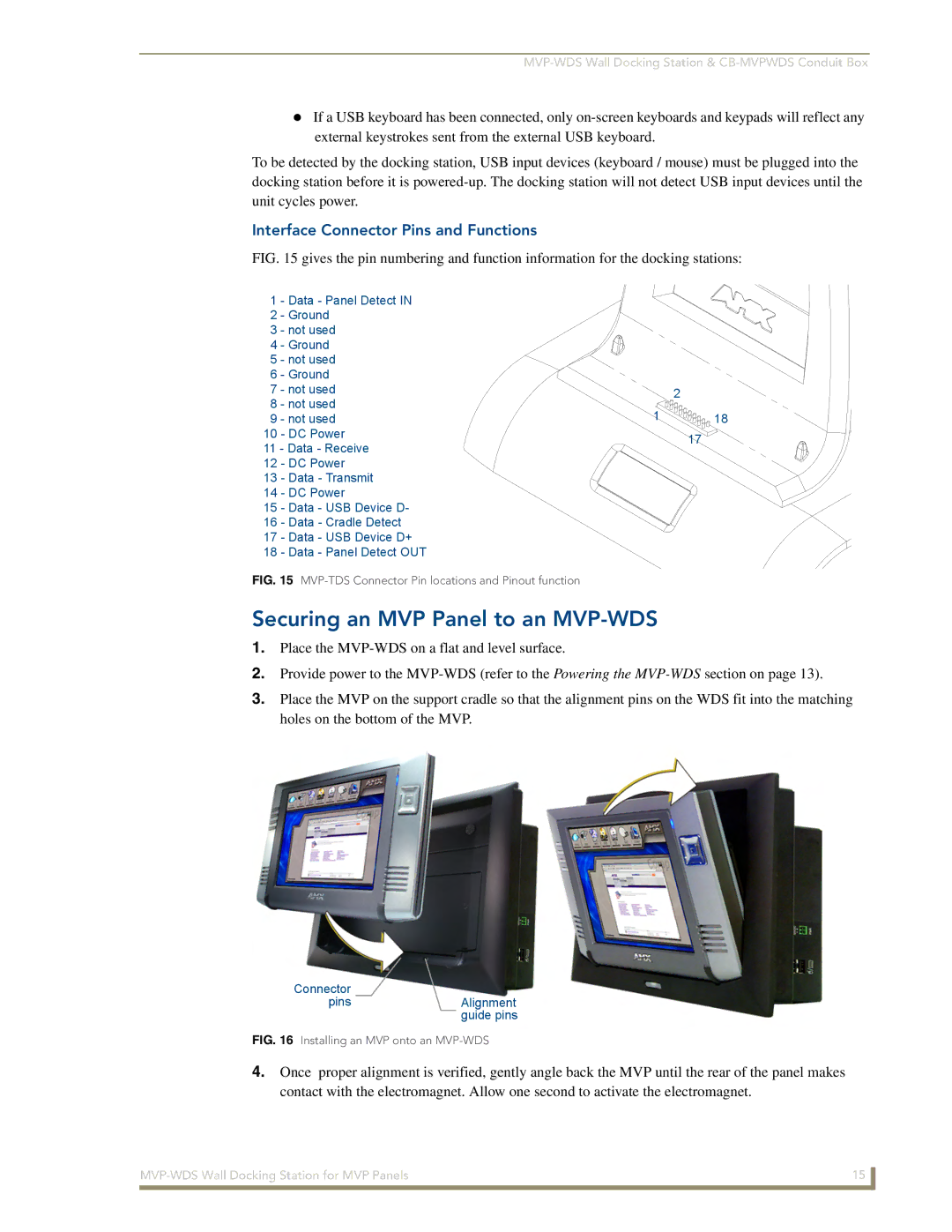
FIG. 15 gives the pin numbering and function information for the docking stations:
1 | - Data - Panel Detect IN |
|
| |
2 | - Ground |
|
| |
3 | - not used |
|
| |
4 | - Ground |
|
| |
5 | - not used |
|
| |
6 | - Ground |
|
| |
7 | - not used |
| 2 | |
8 | - not used |
| ||
1 | 18 | |||
9 | - not used | |||
10 | - DC Power |
| 17 | |
11 - Data - Receive |
| |||
|
| |||
12 | - DC Power |
|
| |
13 | - Data - Transmit |
|
| |
14 | - DC Power |
|
| |
15 | - Data - USB Device D- |
|
| |
16 | - Data - Cradle Detect |
|
| |
17 | - Data - USB Device D+ |
|
| |
18 | - Data - Panel Detect OUT |
|
| |
FIG. 15 MVP-TDS Connector Pin locations and Pinout function
Securing an MVP Panel to an MVP-WDS
1.Place the
2.Provide power to the
3.Place the MVP on the support cradle so that the alignment pins on the WDS fit into the matching holes on the bottom of the MVP.
Connector
pinsAlignment guide pins
FIG. 16 Installing an MVP onto an MVP-WDS
4.Once proper alignment is verified, gently angle back the MVP until the rear of the panel makes contact with the electromagnet. Allow one second to activate the electromagnet.
15 | |
|
|