Installing the MVP-WDS in a CB-MVPWDS Conduit Box
The conduit box must be mounted prior to continuing this section. Refer to the Installing the
The faceplate must be removed prior to any surface installation (see the Removing the MVP- WDS Faceplate section on page 5).
Verify that the USB and power cables have been threaded through the knockouts on the right of the conduit box. Leave enough slack in the wiring to accommodate
1.Connect the
Verify that the terminal end of the power cable is not connected to a power source before plugging in the
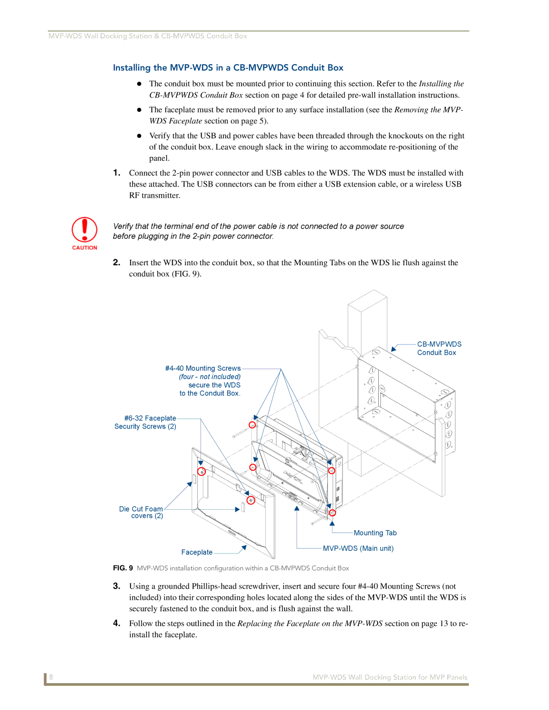
2.Insert the WDS into the conduit box, so that the Mounting Tabs on the WDS lie flush against the conduit box (FIG. 9).
Security Screws (2)
Die Cut Foam covers (2)
Faceplate ![]()
![]()
![]()
Conduit Box
![]() Mounting Tab
Mounting Tab
FIG. 9 MVP-WDS installation configuration within a CB-MVPWDS Conduit Box
3.Using a grounded
4.Follow the steps outlined in the Replacing the Faceplate on the
8 |