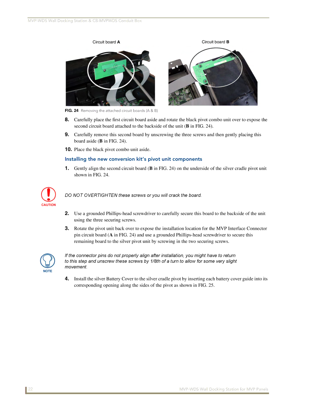
Circuit board A | Circuit board B |
FIG. 24 Removing the attached circuit boards (A & B)
8.Carefully place the first circuit board aside and rotate the black pivot combo unit over to expose the second circuit board attached to the backside of the unit (B in FIG. 24).
9.Carefully remove this second board by unscrewing the three screws and then gently placing this board aside (B in FIG. 24).
10.Place the black pivot combo unit aside.
Installing the new conversion kit’s pivot unit components
1.Gently align the second circuit board (B in FIG. 24) on the underside of the silver cradle pivot unit shown in FIG. 24.
DO NOT OVERTIGHTEN these screws or you will crack the board.
2.Use a grounded
3.Rotate the pivot unit back over to expose the installation location for the MVP Interface Connector pin circuit board (A in FIG. 24) and use a grounded
If the connector pins do not properly align after installation, you might have to return to this step and unscrew these screws by 1/8th of a turn to allow for some very slight movement.
4.Install the silver Battery Cover to the silver cradle pivot by inserting each battery cover guide into its corresponding opening along the sides of the pivot as shown in FIG. 25.
22 |